
Method for electroplating lead frame

A lead frame and frame technology, which is applied in the direction of electrolytic organic material plating, circuits, electrical components, etc., can solve the problems of large amount of dry film, easy to be plated, unfavorable mass production of lead frames, etc., to ensure the quality of electroplating, electroplating low cost effect

Active Publication Date: 2010-05-12
NINGBO KANGQIANG ELECTRONICS CO LTD
View PDF0 Cites 3 Cited by
  • Summary
  • Abstract
  • Description
  • Claims
  • Application Information

AI Technical Summary

Problems solved by technology

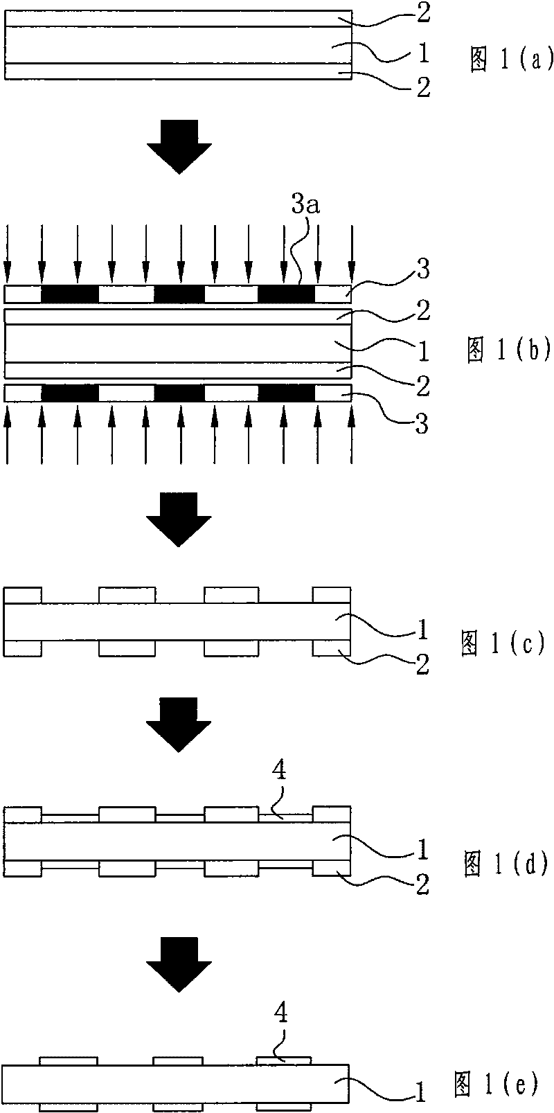
The electroplating method (process diagram as shown in Figure 1) of prior art integrated circuit lead frame is: paste dry film; Exposure; Development; Electroplating; process steps to form an electroplating mask, but due to the high price of the dry film and the need to paste the dry film on the surface of the integrated circuit lead frame during the process, the dry film corresponding to the area to be electroplated is removed after exposure and development. The amount of dry film is large, so the cost of electroplating is very high, which is not conducive to the mass production of lead frames; at the same time, because the side of the lead frame cannot be pasted with dry film, it is easy to be plated during electroplating, which is easy to cause short circuit of the circuit , leading to lower yield

Method used


Image

  • Method for electroplating lead frame
  • Method for electroplating lead frame
  • Method for electroplating lead frame

Examples


Embodiment 1

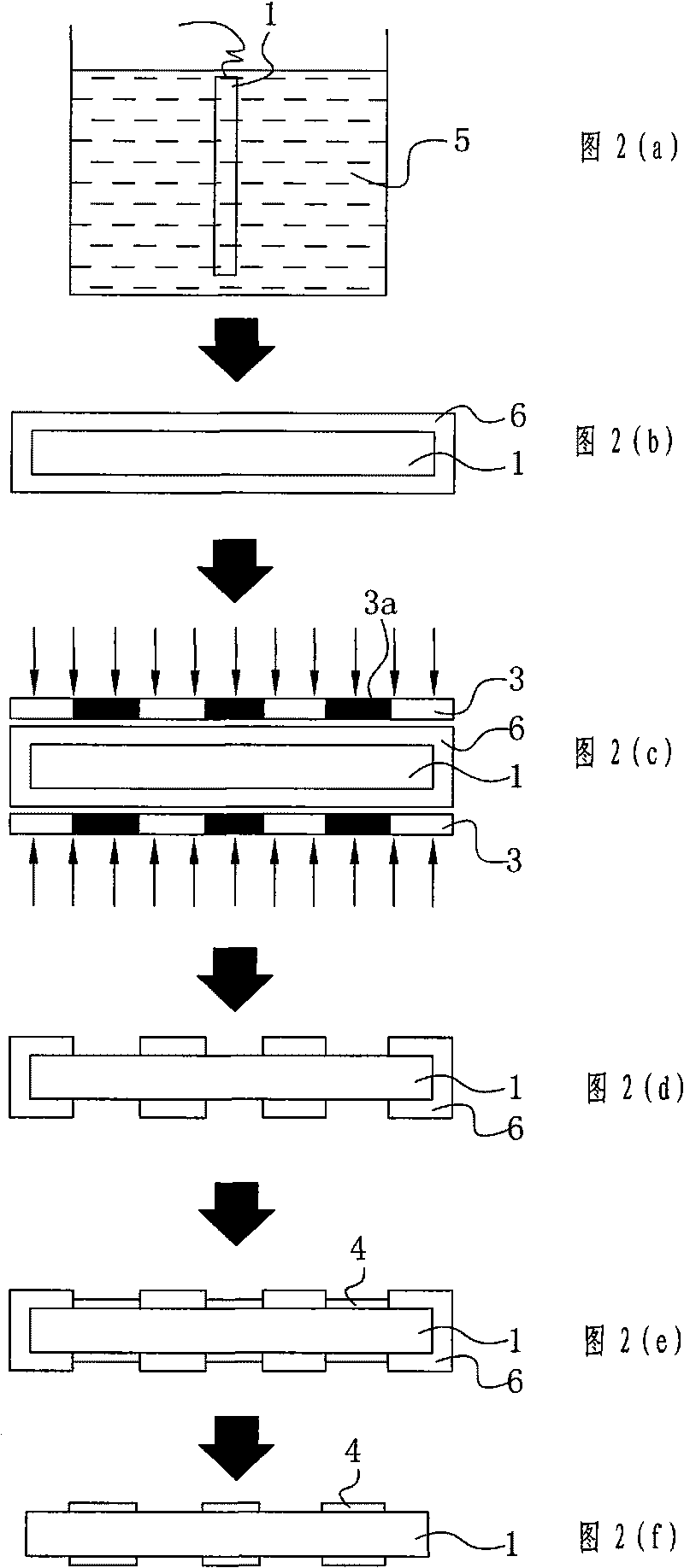
[0025] 1. prepare wet film solution 5, the concentration of described wet film solution 5 is 55%, film is the model that American Rohm and Haas Company produces is EAGLE TM 2100 ED PHOTORESIST;

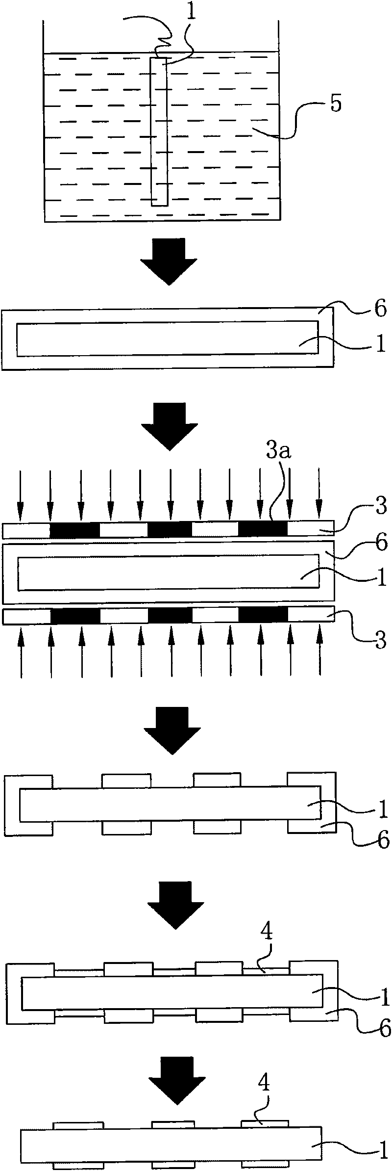
[0026] ②. After the lead frame 1 is connected to the wire, put it into the wet film solution 5 as shown in Figure 2(a) for electroplating, the electroplating time is 10-12 seconds, and the temperature is 40°C-50°C, as shown in Figure 2(b ) shows that after electroplating, the surrounding surfaces of the lead frame 1 are coated with a film layer 6;

[0027] ③. Wash the electroplated lead frame 1 with clean water, and dry it in a conventional sawing furnace, the drying temperature is 90°C-100°C, and the drying time is 80-90 seconds;

[0028] ④. Expose the dried lead frame 1. The exposure is required to be carried out in a dust-free environment. When exposing as shown in FIG. 2(c), put a glass mask 3 on the upper and lower surfaces of the lead frame 1. 3 is provided with a light-shiel...

Embodiment 2

[0034] 1. prepare wet film solution 5, the concentration of described wet film solution 5 is 65%, film is the model that American Rohm and Haas Company produces is EAGLE TM 2100 ED PHOTORESIST;

[0035] ②. After the lead frame 1 is connected to the wire, put it into the wet film solution 5 for electroplating as shown in Figure 2(a). ) shows that after electroplating, the surrounding surfaces of the lead frame 1 are coated with a film layer 6;

[0036] ③. Clean the lead frame 1 after electroplating with clean water, and dry it in a conventional sawing furnace, the drying temperature is 95°C-105°C, and the drying time is 60-80 seconds;

[0037] ④. Expose the dried lead frame 1. The exposure is required to be carried out in a dust-free environment. When exposing as shown in FIG. 2(c), put a glass mask 3 on the upper and lower surfaces of the lead frame 1. 3 is provided with a light-shielding part 3a, the light-shielding part 3a prevents the corresponding film layer 6 from bein...

Embodiment 3

[0043] 1. prepare wet film solution 5, the concentration of described wet film solution 5 is 75%, film is the model that American Rohm and Haas Company produces is EAGLE TM 2100 ED PHOTORESIST;

[0044] ②. After the lead frame 1 is connected to the wire, put it into the wet film solution 5 for electroplating as shown in Figure 2(a). ) shows that after electroplating, the surrounding surfaces of the lead frame 1 are coated with a film layer 6;

[0045] ③. Clean the lead frame 1 after electroplating with clean water, and dry it in a conventional sawing furnace, the drying temperature is 100°C-110°C, and the drying time is 30-60 seconds;

[0046]④. Expose the dried lead frame 1. The exposure is required to be carried out in a dust-free environment. When exposing as shown in FIG. 2(c), put a glass mask 3 on the upper and lower surfaces of the lead frame 1. 3 is provided with a light-shielding part 3a, and the light-shielding part 3a prevents the corresponding film layer 6 from ...


PUM


Abstract

The invention discloses a method for electroplating a lead frame, which comprises the following steps: (1) preparing a wet-film solution (5); (2) electroplating a film layer on the lead frame; (3), cleaning and drying the lead frame; (4) exposing the lead frame; (5) developing the lead frame; (6) electroplating a metal layer on the lead frame; (7) performing film removal treatment; and (8) cleaning and air-drying the lead frame. Compared with the prior art, the method has the advantages that: because a mask treatment is performed on the lead frame by using an electroplated film before the metal layer is plated on the lead frame, the side edge of the lead frame is also electroplated with a mask, a metal plating layer cannot be plated on the side edge of the lead frame when the metal layer is electroplated on the lead frame, and the electroplating quality of the lead frame is ensured; and simultaneously the price of the film is lower than that of a dry film. Thus, the method has a low electroplating cost, is favorable for batch production and has a high yield of finished products.

Description

Technical field: [0001] The invention relates to a method for manufacturing a lead frame, in particular to an electroplating method for a lead frame whose surface is partially electroplated. Background technique: [0002] Lead frames of integrated circuits (such as QFN-quad flat no-lead package, QFP-four-side pin flat package, etc.) are the basic components for manufacturing integrated circuit semiconductor components. In order to meet the needs of manufacturing integrated circuit semiconductor components, the local area of ​​the lead frame surface of the integrated circuit needs to be plated with metal silver or nickel-palladium gold, and the rest of the part does not require plating, otherwise it cannot meet the needs of manufacturing integrated circuit semiconductor components, so the integrated circuit lead When the frame is electroplated, an electroplating mask needs to be used to protect the part of the surface that does not need to be electroplated. The electroplatin...

Claims


Application Information

Patent Timeline
Patent Type & Authority Applications(China)
IPC IPC(8): H01L21/48C25D9/02
Inventor 郑康定邓道斌马叶军
Owner NINGBO KANGQIANG ELECTRONICS CO LTD
Learn More