Method and driver for determining drive values for driving a lighting device

a technology for lighting devices and drive values, applied in the direction of electric variable regulation, process and machine control, instruments, etc., can solve the problems of system not being suitable for driving lighting devices, waste of power to generate light, etc., and achieve the effect of overcoming or at least alleviating the problem

Active Publication Date: 2011-09-06
SIGNIFY HLDG BV
View PDF10 Cites 25 Cited by
  • Summary
  • Abstract
  • Description
  • Claims
  • Application Information

AI Technical Summary

Benefits of technology

[0010]The differently colored LEDs preferably includes at least a red narrow banded light emitting diode, at least a green narrow banded light emitting diode, and at least a blue narrow banded light emitting diode. However, the skilled addressee realizes that it also would be possible to use other types of light sources such as organic light emitting diodes (OLEDs), polymeric light emitting diodes (PLEDs), inorganic LEDs, lasers, or a combination thereof, as well as a wide-band (direct or phosphor converted) LED and wide-band (phosphor converted) white LEDs. An advantage with using narrow banded LEDs in a lighting device as described above is that it is possible to generate saturated colors. However, the skilled addressee realizes that a wide-band LED also can give a saturated color
[0016]According to prior art, the process of determining drive values for driving a lighting device at a desired color and brightness, where the light emitted by the lighting device is produced by a plurality of differently colored LEDs, did not take into account the color shift produced when using a different current drive level then the first drive current level. However, the present invention provides for the possibility to limit the number of necessary computational steps for determining preferred drive currents. Furthermore, an increased number of current level and / or differently colored LEDs would only slightly increase the computational cost. An advantage with the present invention is that it is possible to select the appropriate drive currents and duty cycles in a forward manner, without the need for a feedback control system. It is however of course possible to include such a feedback control system. Another advantage is that the current through the LEDs are minimized which relaxes the timing and signal integrity requirements as well as prolonging the life time of the LEDs due to a lower substrate temperature (a higher drive current amplitude gives a higher substrate temperature of the LED).
[0022]Each of the current sources can be activated with an individual pulse width modulated signal. In this way, the PWM activation signals are used for Pulse Width Modulation (PWM) and Pulse Amplitude Modulation (PAM) at the same time, keeping the implementation very simple. Only two current sources are used above, however, the skilled addressee recognizes that the implementation can be further expanded, where N current sources generates 2N current levels.

Problems solved by technology

A disadvantage of using only PWM is that the LED is always used at the same current level, which may not be the most efficient current level, meaning that the power is wasted to generate light.
However, such a system is not suitable for driving a lighting device comprising of a plurality of differently colored LEDs since a shift in amplitude also results in a significant color shift.

Method used


Image

  • Method and driver for determining drive values for driving a lighting device
  • Method and driver for determining drive values for driving a lighting device
  • Method and driver for determining drive values for driving a lighting device

Examples


Embodiment Construction

[0030]The present invention will now be described more fully hereinafter with reference to the accompanying drawings, in which currently preferred embodiments of the invention are shown. This invention may, however, be embodied in many different forms and should not be construed as limited to the embodiments set forth herein; rather, theses embodiment are provided for thoroughness and completeness, and fully convey the scope of the invention to the skilled addressee. Like numbers refer to like elements throughout.

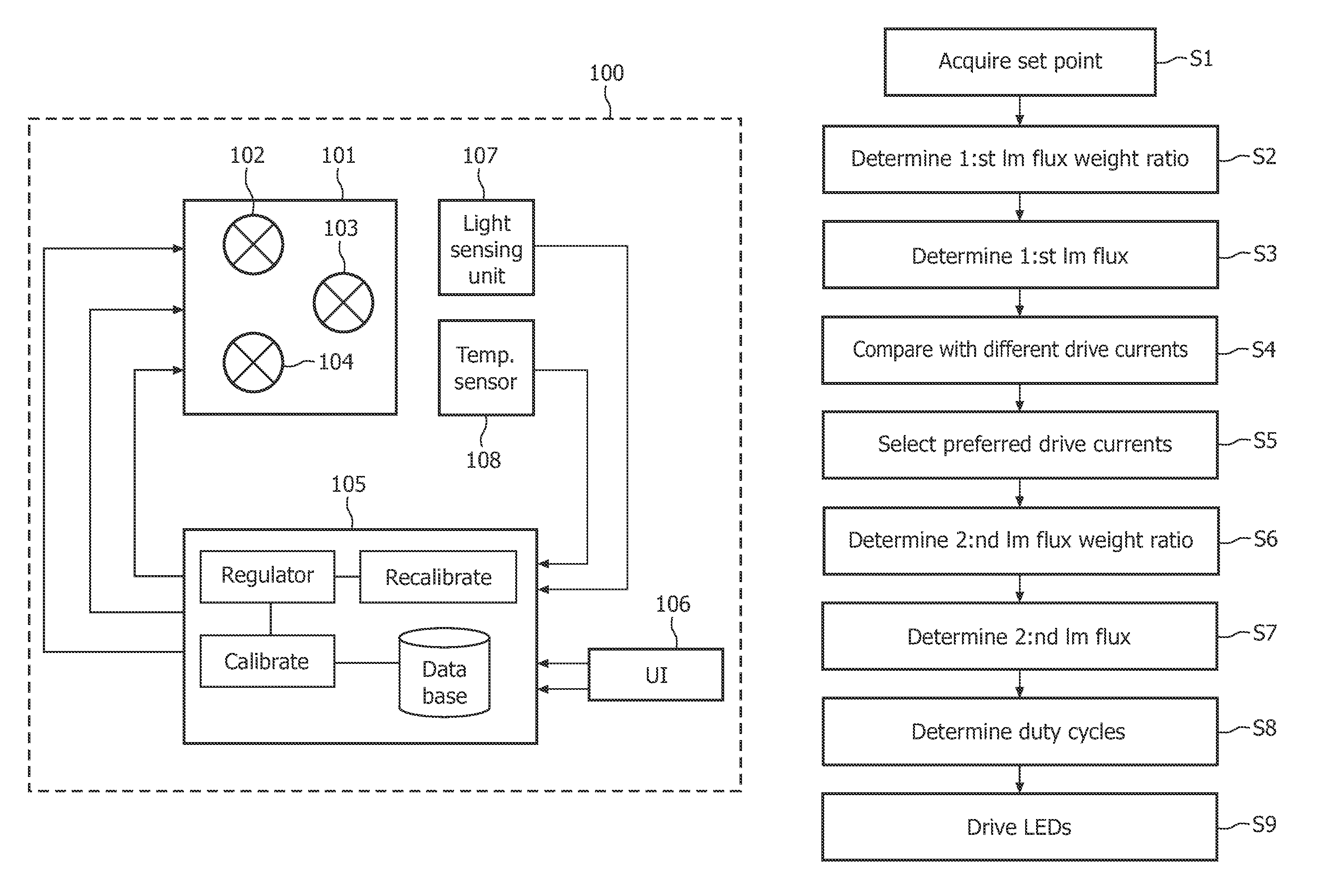
[0031]Referring now to the drawings and to FIG. 1 in particular, there is depicted a block diagram of an adjustable color illumination system 100, arranged in accordance with a currently preferred embodiment of the present invention. In the exemplary embodiment, the illumination system 100 comprises a lighting device 101 comprising of three differently colored light emitting diodes of the colors red 102, green 103 and blue 104. The lighting device 101 is in turn connected t...


PUM


Abstract

The present invention relates to a method for determining drive values for driving a lighting device at a desired brightness and color. The method comprising the steps of determining a first luminous flux weight ratio based on the desired color and a first drive current for driving each of the differently colored LEDs, determining a first luminous flux for each of the differently colored LEDs based on the desired brightness and the first luminous flux weight ratio, comparing, for each of the differently colored LEDs, the first luminous flux with a nominal luminous flux for a plurality of different drive currents, selecting, for each of the differently colored LEDs, a preferred drive current that at least can produce the first luminous flux, determining a second luminous flux weight ratio based on the desired color and the selected drive currents for each of the differently colored LEDs, determining a second luminous flux for each of the differently colored LEDs based on the desired brightness and the second luminous flux weight ratio, and determining a duty cycle for each of the differently colored LEDs at the selected drive currents, wherein the selected currents at the determined duty cycles produces the second luminous flux for each of the differently colored LEDs. The present invention provides for the possibility to limit the number of necessary computational steps for determining preferred drive currents. Furthermore, an increase in number of current level and / or differently colored LEDs would only slightly increase the computational cost.

Description

FIELD OF THE INVENTION[0001]The present invention relates to a method for determining drive values for driving a lighting device at a desired brightness and color. The present invention also relates to a corresponding driver for determining drive values for driving a lighting device.DESCRIPTION OF THE RELATED ART[0002]Recently, much progress has been made in increasing the brightness of light emitting diodes (LEDs). As a result, LEDs have become sufficiently bright and inexpensive to serve as a light source in for example lighting system such as lamps with adjustable color, direct view Liquid Crystal Displays (LCDs), and in front and rear projection displays.[0003]By mixing differently colored LEDs any number of colors can be generated, e.g. white. An adjustable color lighting system is typically constructed by using a number of primary colors, and in one example, the three primaries red, green and blue are used. The color of the generated light is determined by which of the LEDs th...

Claims


Application Information

Patent Timeline
Patent Type & Authority Patents(United States)
IPC IPC(8): H05B37/02H05B41/36H05B39/04H05B44/00
CPCH05B33/0818H05B33/0863H05B33/0869G09G3/3413H05B33/0872G09G2320/0693G09G2320/041G09G2320/0666H05B45/22H05B45/28H05B45/37
Inventor DE RIJCK, ALEXANDER CHRISTIAANVAN WOUDENBERG, ROELPEETERS, HENRICUS MARIEDEURENBERG, PETER HUBERTUS FRANCISCUS
Owner SIGNIFY HLDG BV
Why Eureka
Try Eureka