Eureka AIR delivers breakthrough ideas for toughest innovation challenges, trusted by R&D personnel around the world.

System and method for providing persistent node names

Active Publication Date: 2011-09-06
NETWORK APPLIANCE INC
View PDF61 Cites 6 Cited by
  • Summary
  • Abstract
  • Description
  • Claims
  • Application Information

AI Technical Summary

Benefits of technology

[0012]By storing the node name in the root volume of the storage system, any of the hardware associated with the storage system, except the root volume, may be replaced or modified without affecting the node name associated with the storage system. This enables clients of a storage system to continue to access the storage system by using the persistent node name without referring to its internal routing / directory information.

Problems solved by technology

As each device connected to a Fibre Channel network has a unique node name, this hard encoding of the node name prevents duplicate node names from appearing on the same Fibre Channel switching fabric, which can lead to routing errors and data loss.
A noted disadvantage of the conventional hard encoding of the node name is that should a storage system be replaced, the clients of that system need to update their internal contact information as the new storage system will have a different node name.
Similarly, if a storage system that is serving data to a set of original clients is taken offline and then reactivated, but with a differing set of volumes of data, the original clients may subsequently direct data access requests to the incorrect storage system.
Furthermore, if storage systems are configured as partners of a cluster and a failover situation arises such that a functioning cluster partner assumes control of the disks and manages data access requests of a failed cluster partner, a new node name will appear to be associated with that failed partner.
The disadvantages described above are more noticeable when individual network interface controllers (NICs) or host bus adapters (HBAs) of a given storage system are replaced or swapped.
A similar problem arises when a HBA / NIC is then moved from an original storage system to a second storage system.
Clients of the original storage system thereafter direct their data access requests to the second storage system, which is not adapted to accept or process these data access requests.
Thus, use of conventional, hard-coded, WWNs as node names in various network configurations may result in additional client-side configuration issues to manage in order to permit the clients to continue to properly access data stored on a storage system.
Such client-side configuration is rather burdensome and, therefore, undesirable.

Method used


Image

  • System and method for providing persistent node names
  • System and method for providing persistent node names
  • System and method for providing persistent node names

Examples


Embodiment Construction

A. Network Environment

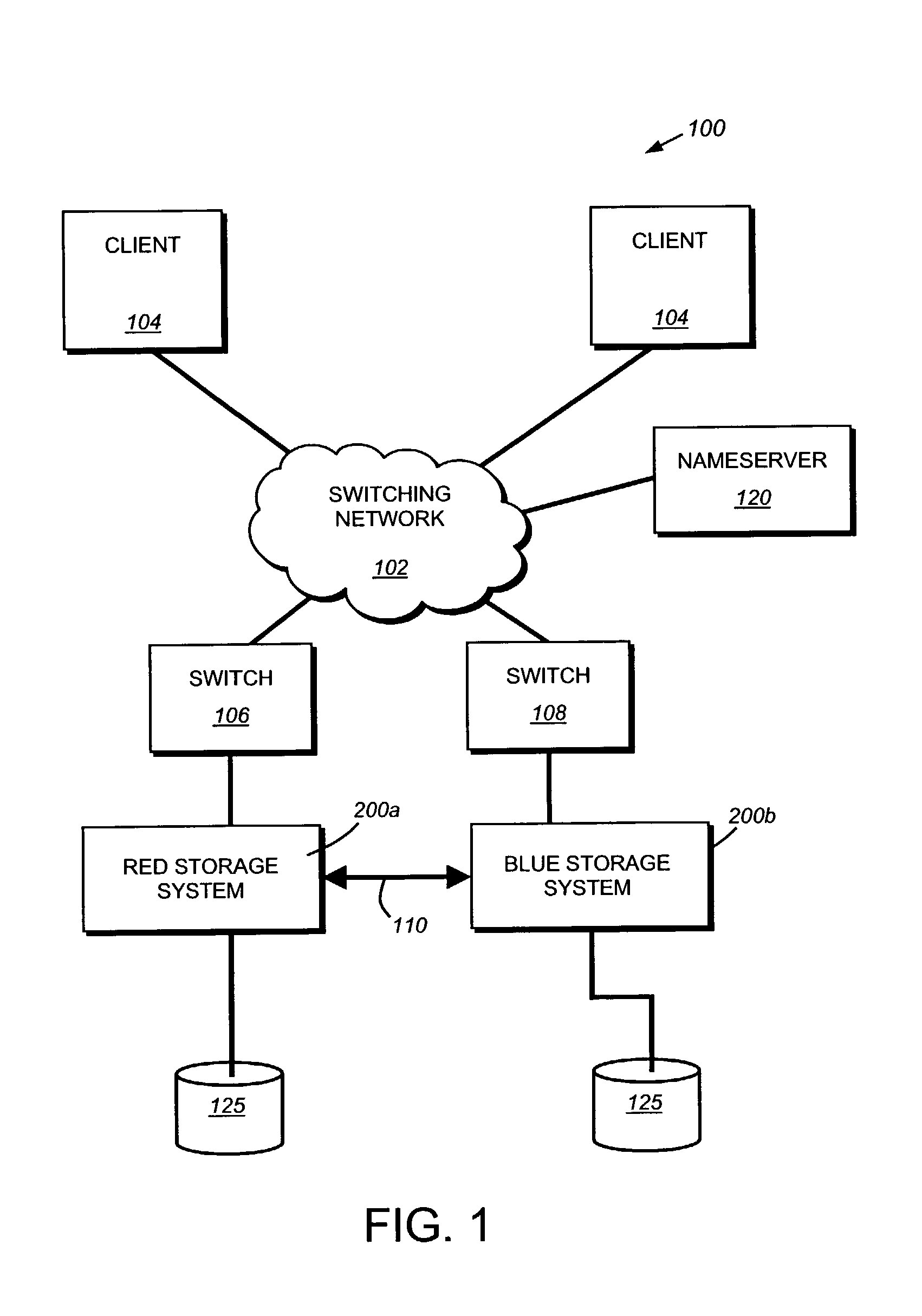
[0021]FIG. 1 is a schematic block diagram of an exemplary network environment 100 in which the principles of the present invention are implemented. The network 100 is based around a network cloud 102 configured as, e.g., a Fibre Channel (FC) switching network. FC is a set of related standards defining a transport service for a variety of data access protocols. Attached to the network cloud are a number of switches, 106 and 108, which connect to various FC devices, such as Red storage system 200 and Blue storage system 200. A number of clients 104 are also interconnected with the network cloud.

[0022]A client 104 may be a general-purpose computer, such as a PC or a workstation, or a special-purpose computer, such as an application server, configured to execute applications over an operating system that includes block access protocols. In this illustrative embodiment, Red storage system 200 and Blue storage system 200 are connected as two nodes of a storage system...


PUM


Abstract

A system and method for providing persistent node names is provided. The system and method stores the node name associated with a given storage system in the root volume associated with the storage system. Thus various components of the storage appliance may be modified without changing the node name associated with a given storage system. This enables clients to have a consistent and persistent node name to connect to in a given network environment.

Description

FIELD OF THE INVENTION[0001]The present invention relates to storage systems and, particularly to storage systems operating on a Fibre Channel network.BACKGROUND OF THE INVENTION[0002]A storage system is a computer that provides storage service relating to the organization of information on writable persistent storage devices, such as memories, tapes or disks. The storage system is commonly deployed within a storage area network (SAN) to or a network attached storage (NAS) environment. When used within a NAS environment, the storage system may be embodied as a file server including an operating system that implements a file system to logically organize the information as a hierarchical structure of directories and files on, e.g. the disks. Each “on-disk” file may be implemented as a set of data structures, e.g., disk blocks, configured to store information, such as the actual data for the file. A directory, on the other hand, may be implemented as a specially formatted file in which...

Claims


Application Information

Patent Timeline
IPC IPC(8): G06F15/177G06F15/173
CPCH04L67/1097
Inventor LEE, HERMANLENT, ARTHUR F.
Owner NETWORK APPLIANCE INC
Why Eureka
Eureka Blog
Learn More