X-linked lift mechanism

a technology of lifting mechanism and x-linked, which is applied in the field of x-linked lifting mechanism, can solve the problems of difficulty in additionally disposing other functional mechanism components, difficulty in abovementioned difficulty, so as to achieve the effect of preventing the drop of the lift frame, preventing the deflection, and high degree of layout freedom

Active Publication Date: 2011-09-13
PARAMOUNT BED CO LTD
View PDF11 Cites 62 Cited by
  • Summary
  • Abstract
  • Description
  • Claims
  • Application Information

AI Technical Summary

Benefits of technology

[0015]In the present invention, all the lift drive components comprising the drive member provided with the boost arms and the drive arms and the lineal′ actuator are installed on the other lateral side of the first links and the second links. Therefore, the lift frame is supported like a cantilever, and on the one lateral side of the first links and the second links, a space free from the lift drive components can be formed. Consequently, the degree of freedom of the layout is high, since, for example, other functional mechanism components can be disposed additionally in the space.
[0016]Further, in the case where the lift frame is supported at a low position, the boost arms projected from the interlocking member support the second links on the one lateral side. Therefore, the lift frame can be supplied like a simple supported beam, and even in the case where the load on the lift frame is large, deflection can be prevented.
[0017]Further, the lift frame is raised when the lineal actuator acts in the direction to elongate itself. Therefore, when the linear actuator is broken, buckling deformation occurs, and dropping of the lift frame can be prevented.
[0018]Further, in the case where the lift frame is supported at a low position, the angle formed between the direction of the force by the moving member of each of the boost arms connected with the drive member and the tangential direction of the wall face of the corresponding guide member can be made large, and it can be prevented that an excess load acts on the linear actuator. Particularly in the case where the guide routes are adequately projected like crests, the load acting on the linear actuator can be averaged.

Problems solved by technology

Therefore, it is difficult to additionally dispose other functional mechanism components.
Particularly in the case where the lift drive components are enlarged while it is intended to keep the lift frame at a position as low as possible in the state where the lift frame is fully lowered and also to keep the lift frame at a position as high as possible at the longest stroke, i.e., in the state where the lift frame is fully raised, the abovementioned difficulty is further intensified.
2. In the configuration wherein the lift frame is raised when the lineal′ actuator acts in the direction to shorten itself, there is a dangerous possibility that if the lineal′ actuator should be broken, the lift frame may drop.

Method used


Image

  • X-linked lift mechanism
  • X-linked lift mechanism
  • X-linked lift mechanism

Examples


Embodiment Construction

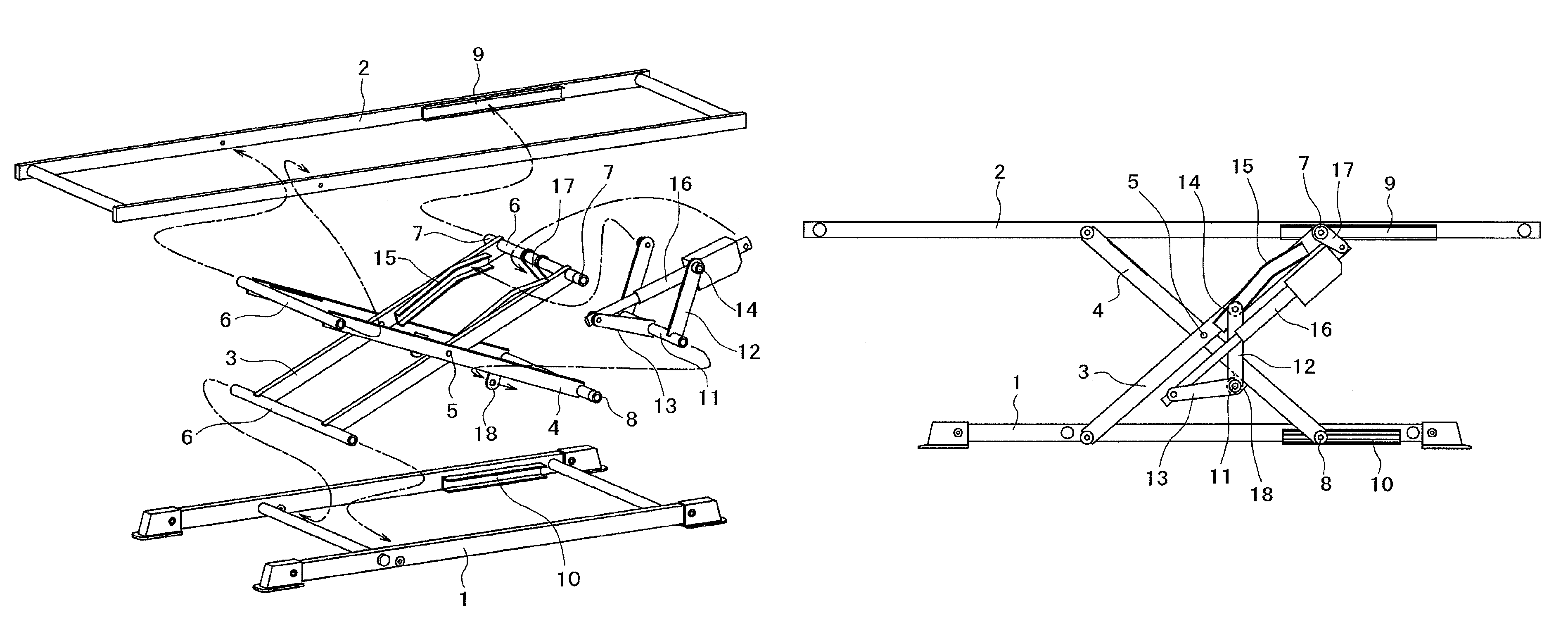
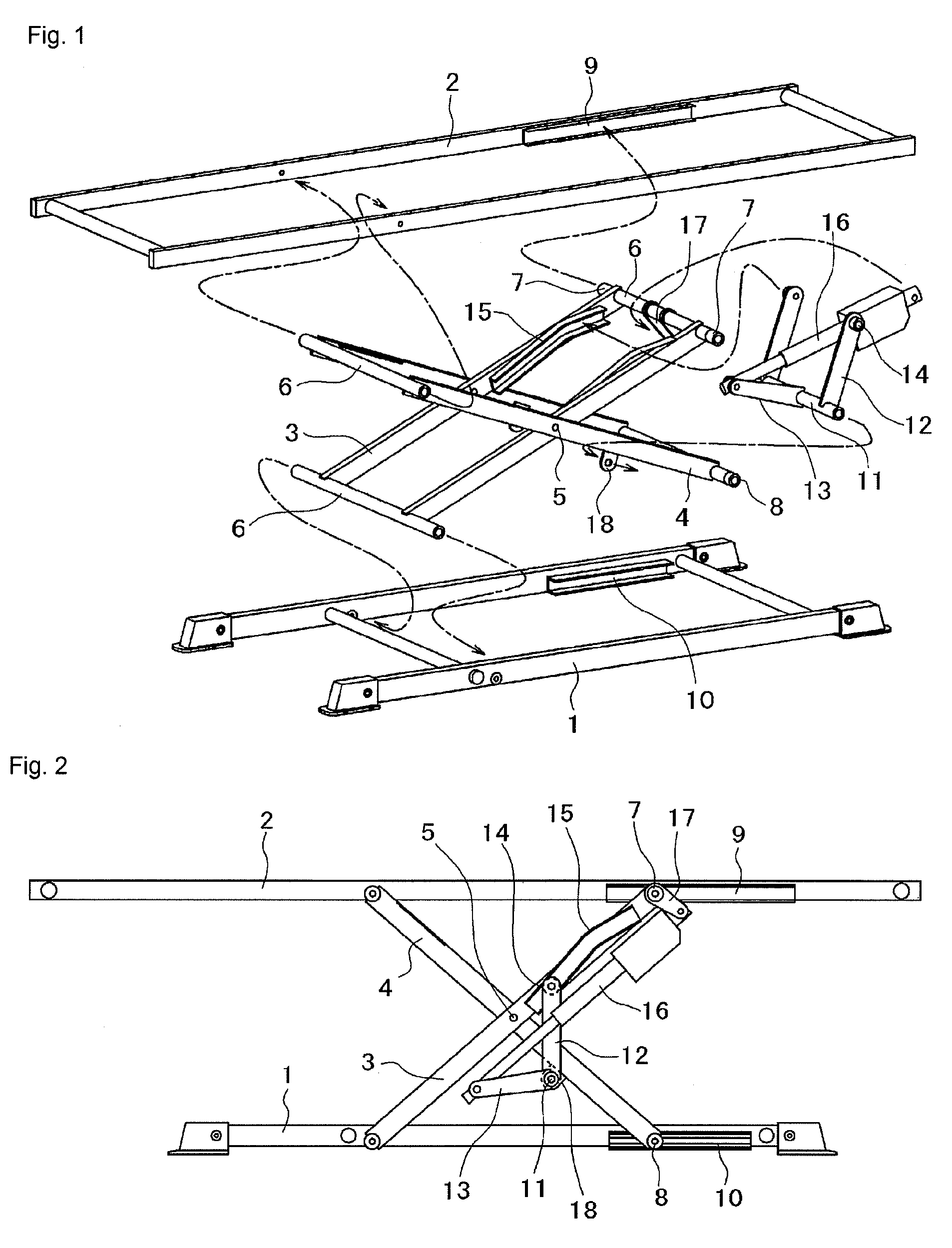
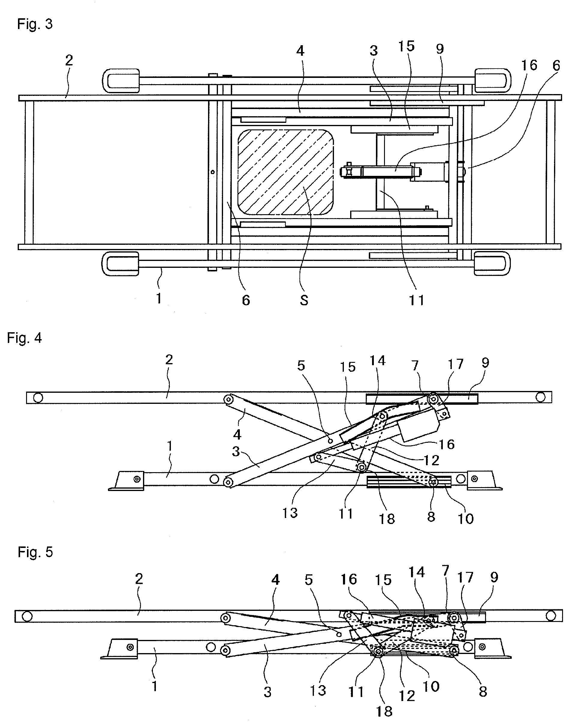
[0054]Modes for carrying out the X-linked lift mechanism of this invention are explained below with reference to FIGS. 1 to 11.

[0055]First of all, FIGS. 1 to 5 show a first embodiment. Reference numeral 1 indicates a base frame, and reference numeral 2 indicates a lift frame. In the case where the article constituting the lift mechanism of this invention is a bed, the lift frame 2 is a bottom support frame for supporting the bottom of the bed, and if the article is a lift table, the lift frame 2 is a table.

[0056]First links 3 and second links 4 are connected with each other between the base frame 1 and the lift frame 2 at pivots 5 in such a manner that the first and second links can be pivotally rotated. The first links 3 are provided in parallel to each other as a pail', and the second links 4 are also provided in parallel to each other as a pair. The first links are connected with each other by connecting rods 6, and the second links are also connected with each other by other con...


PUM


Abstract

An X-linked lift mechanism having first links (3) and second links (4) constituting an X-linked mechanism between a base frame (1) and a lift frame (2). A drive member (11) is pivotally rotatably installed between the other lateral side portions of the second links and is connected with boost arms (12) and a drive arm (13). Guide members (15) are provided for guiding the moving members (14) installed at the ends of the boost arms. The guide members are installed on the other lateral side portions of the first links in the length direction. Also, a linear actuator is provided so as to extend between the other lateral side of the first links and the drive arm.

Description

BACKGROUND OF THE INVENTION[0001]1. Technical Field[0002]The present invention relates to an X-linked lift mechanism used for a hospital bed, home nursing care bed, facility bed, general bed, consultation seat, lift table, etc.[0003]2. Description of the Related Art[0004]For example, as mechanisms for lifting a lift frame relative to a base frame, as used for a bed or lift table, available are many parallel-linked lift mechanisms using parallel-linked mechanisms and X-linked lift mechanisms using X-linked mechanisms. This invention relates to an X-linked lift mechanism.[0005]In the conventional X-linked lift mechanisms proposed, for example, in Patent Document 1 and Patent Document 2, the respective ends of first links and second links on one lateral side are pivotally rotatably fixed to a base frame and a lift frame, and the moving members installed at the respective ends of the first and second links on the other lateral side are engaged with the guide members installed on the lif...

Claims


Application Information

Patent Timeline
Patent Type & Authority Patents(United States)
IPC IPC(8): A61G7/012
CPCA47C19/04A47C19/045B66F7/065A61G7/1057A61G7/1019A61G1/00A61G13/06B66F7/06
Inventor SHIMADA, TATSUYATAKADA, TOORUTOMIKAWA, JUNKAGEYAMA, DANSASAKI, YURINOMURA, KATSUYOSHI
Owner PARAMOUNT BED CO LTD
Why Eureka
Try Eureka