Noise insulation device for aircraft

Active Publication Date: 2011-09-13
MEYER BRETABCHNEIDER THOMAS J
View PDF37 Cites 3 Cited by
  • Summary
  • Abstract
  • Description
  • Claims
  • Application Information

AI Technical Summary

Benefits of technology

[0004]A noise insulation device for aircraft of the type mentioned at the beg

Problems solved by technology

This produces a considerable amount of noise which has to be shielded, in particular if said test run includes operating the engines at full load.
However, its construction is associated with high costs.
This is because the roof has to cover large distances between the side walls over the entire length of the aircraft i

Method used


Image

  • Noise insulation device for aircraft
  • Noise insulation device for aircraft
  • Noise insulation device for aircraft

Examples


Example

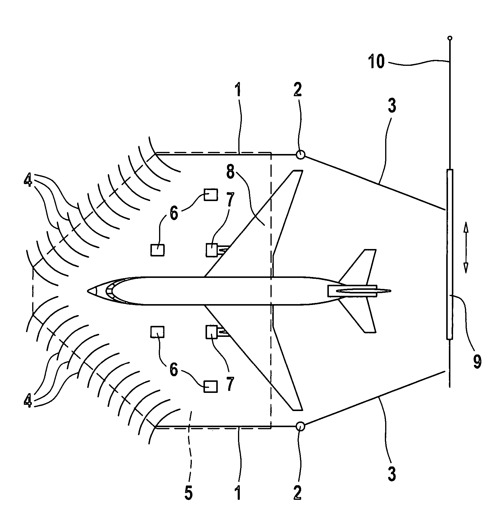
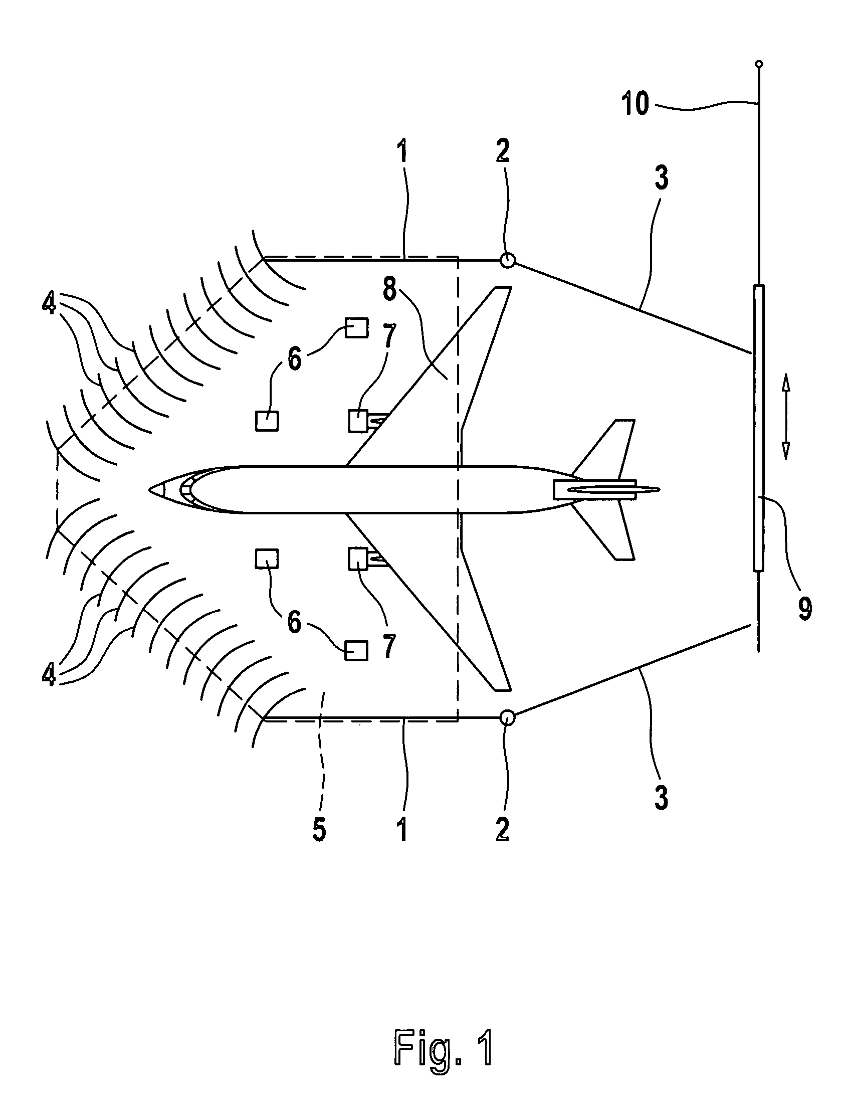
[0027]FIG. 1 shows a first embodiment of the a noise insulation device which has fixed side walls 1, pivotable walls 3, coupled at 2, a group of conducting surfaces 4 and a roof indicated by dashed lines at 5. The roof is supported by means of supports 6 and by the side walls 1 and the conducting surfaces 4.

[0028]The movable walls 3, which can also be guided, for example, in the manner of rolling doors, are shown in FIGS. 1 and 3 in the position in which the engines 7 of the aircraft 8 are to be tested. The aircraft is moved until the wings are in the region below the roof 5. When the aircraft 8 is to be moved out of the noise insulation device or is to be moved into the latter, the walls 3 are pivoted or rolled outward as far as is required.

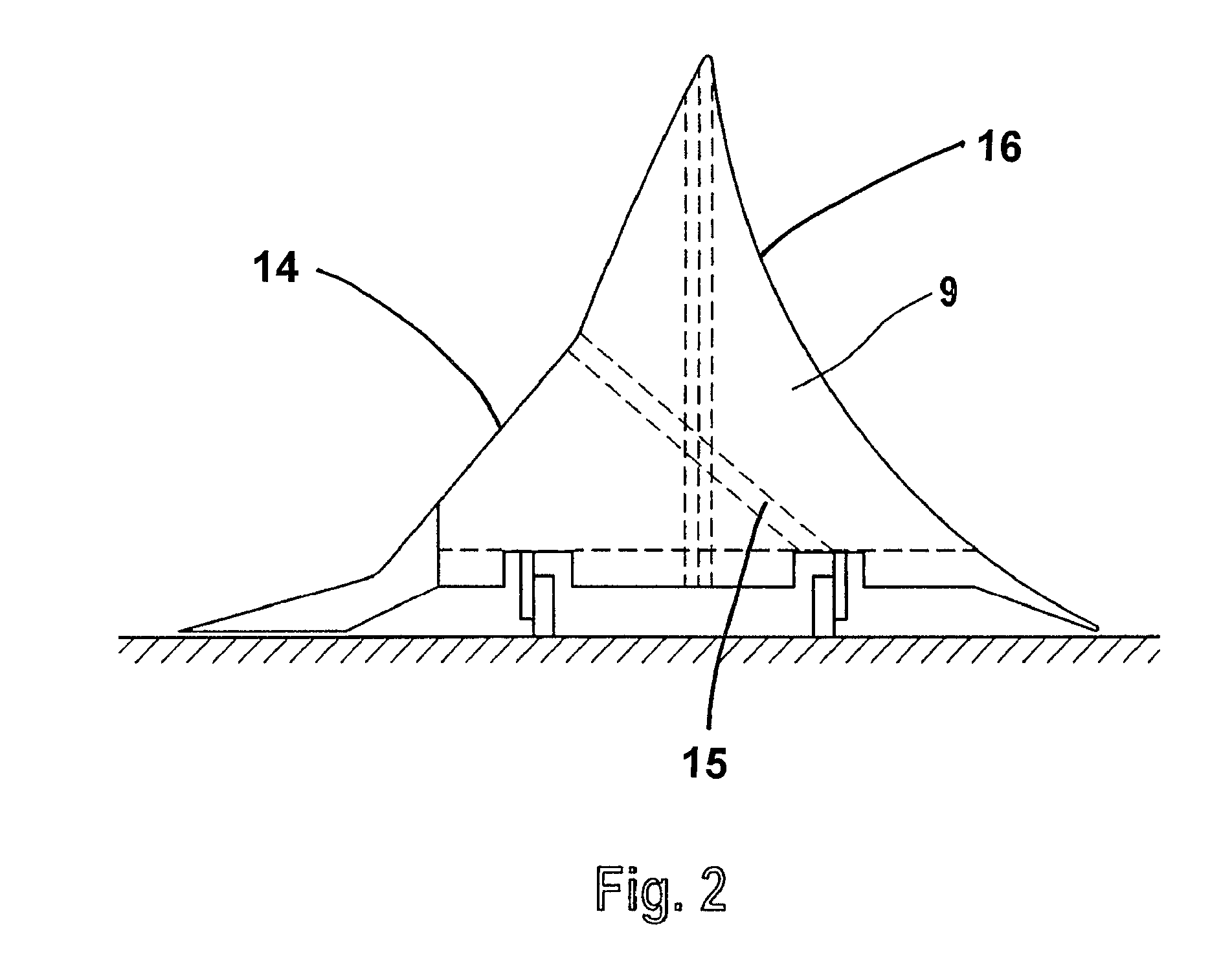
[0029]The rear opening of the noise insulation device can be closed by a movable backside wall 9 which can be moved on rails 10. This backside wall is shown in FIG. 2 from the side. On both sides, it has covering surfaces 14 and 16 which are sui...


PUM


Abstract

Disclosed is a noise insulation device for aircraft, comprising a first opening that is delimited by a series of conducting surfaces whose inner edge is oriented towards the interior of the noise insulation device from a horizontal cross-sectional perspective and whose outer surface is directed towards the side, a roof, and a second opening which is located opposite the first opening and is delimited by walls. The inventive noise insulation device is characterized in that the size of the second opening can be modified by making changes to the walls.

Description

BACKGROUND[0001]After maintenance work, in particular after repairs, aircraft engines have to be tested in a test run. This produces a considerable amount of noise which has to be shielded, in particular if said test run includes operating the engines at full load.[0002]In the case of a known noise insulation device of the type mentioned at the beginning (WO 98 / 06625), the aircraft is brought backwards into a noise insulation hangar. The hangar, which is generally entirely covered by a roof, has to have a considerable height in order to be able to accommodate the rudder unit, or a slot for the rudder unit has to be provided in the roof and then has to be closed after the aircraft is brought into the noise insulation hangar. The opening into which the aircraft is brought is then closed by doors which have conducting surfaces which damp the sound emerging to the front and also deflect the inflowing air in such a manner that it flows approximately in the longitudinal direction of the a...

Claims


Application Information

Patent Timeline
IPC IPC(8): B64F1/26B64F3/00
CPCB64F1/26
Inventor MEYER-BRETSCHNEIDER, THOMAS J.
Owner MEYER BRETABCHNEIDER THOMAS J
Why Eureka
Try Eureka