Drilling rigs with apparatus identification systems and methods

a technology of identification system and drill rig, which is applied in the field of wellbore operation rig system and method, can solve the problems of rfidt so positioned failing and being of no further use, and rfidt so positioned being subjected to damage above ground

Active Publication Date: 2011-09-13
NAT OILWELL VARCO LP
View PDF70 Cites 41 Cited by
  • Summary
  • Abstract
  • Description
  • Claims
  • Application Information

AI Technical Summary

Benefits of technology

[0014]The present invention, in certain aspects, provides an item, apparatus, or tubular, e.g. a piece of drill pipe, with one or more radio frequency identification tags wrapped in heat and impact resistant materials; in one aspect, located in an area 2-3″ in length beginning ½ from the 18 degree taper of the pin and drill pipe tool joint so that the RFIDT (or RFIDT's) is protected from shocks (pressure, impacts, thermal) that may be encountered on a rig, in a wellbore, or during wellbore (e.g. drilling or casing) operations. In one particular aspect, the present invention discloses systems and methods in which a piece of drill pie with threaded pin and box ends has one or more radio frequency identification tags each with an integrated circuit and with an antenna encircling the pin end upset area located exteriorly on the pipe, e.g. in an area ½″-2½″ from a pin end 18 degree taper. The RFIDT (or RFIDT's) is protected by wrapping the entire RFIDT and antenna in a heat resistant material wrapped around the circumference of the tube body and held in place by heat resistant glue or adhesive, e.g. epoxy material which encases the RFIDT. This material is covered with a layer of impact resistant material and wrapped with multiple layers of wrapping material such as epoxy bonded wrap material. Preferably this wrapping does not exceed the tool joint OD. The RFIDT can be (as can be any disclosed herein), in certain aspects, any known commercially-available read-only or read-write radio frequency identification tag and any suitable know reader system, manual, fixed, and / or automatic may be used to read the RFIDT. Such installation of RFIDT's can be carried out in the field, in a factory, on a rig, with no machining necessary. Optionally, a metal tag designating a unique serial number of each item, apparatus, or length of drill pipe located under the wrap with the RFIDT(s) insures “Traceability” is never lost due to failure of the RFIDT(s). Replacement of failed RFIDT's can be carried out without leaving a location, eliminating expensive transportation or trucking costs. Optionally the wrap is applied in a distinctive and / or a bright color for easy identification. Determining whether an item, apparatus, or a tubular or a length of drill pipe or a drill pipe string is RFID-tagged or not is visibly noticeable, e.g. from a distance once the RFIDT's are in place.
[0016]With an RFIDT located in a pipe's pin end as described herein, upon makeup of a joint including two such pieces of pipe, an RFIDT in one pipe's pin end is completely surrounded by pipe material—including that of a corresponding pipe's box end—and the RFIDT is sealingly protected from access by materials flowing through the pipe and from materials exterior to the pipe. The mass of pipe material surrounding the enclosed RFIDT also protects it from the temperature extremes of materials within and outside of the pipe.

Problems solved by technology

Often an RFIDT so positioned fails and is of no further use.
Also, in many instances, an RFIDT so positioned is subjected to damage above ground due to the rigors of handling and manipulation.

Method used


Image

  • Drilling rigs with apparatus identification systems and methods
  • Drilling rigs with apparatus identification systems and methods
  • Drilling rigs with apparatus identification systems and methods

Examples


Embodiment Construction

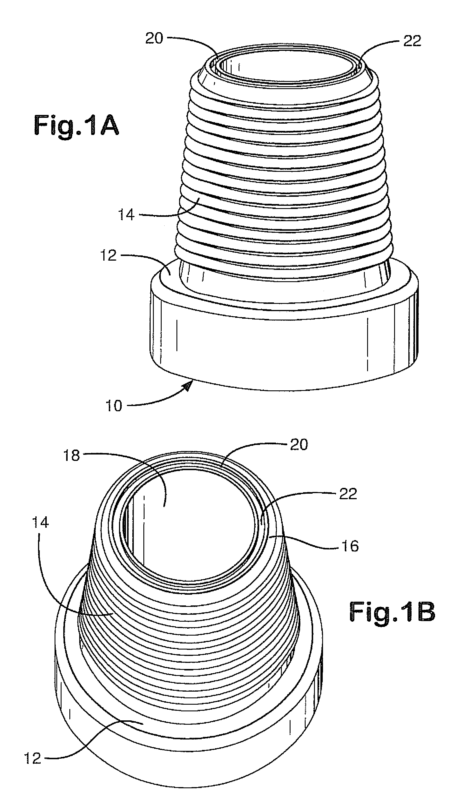
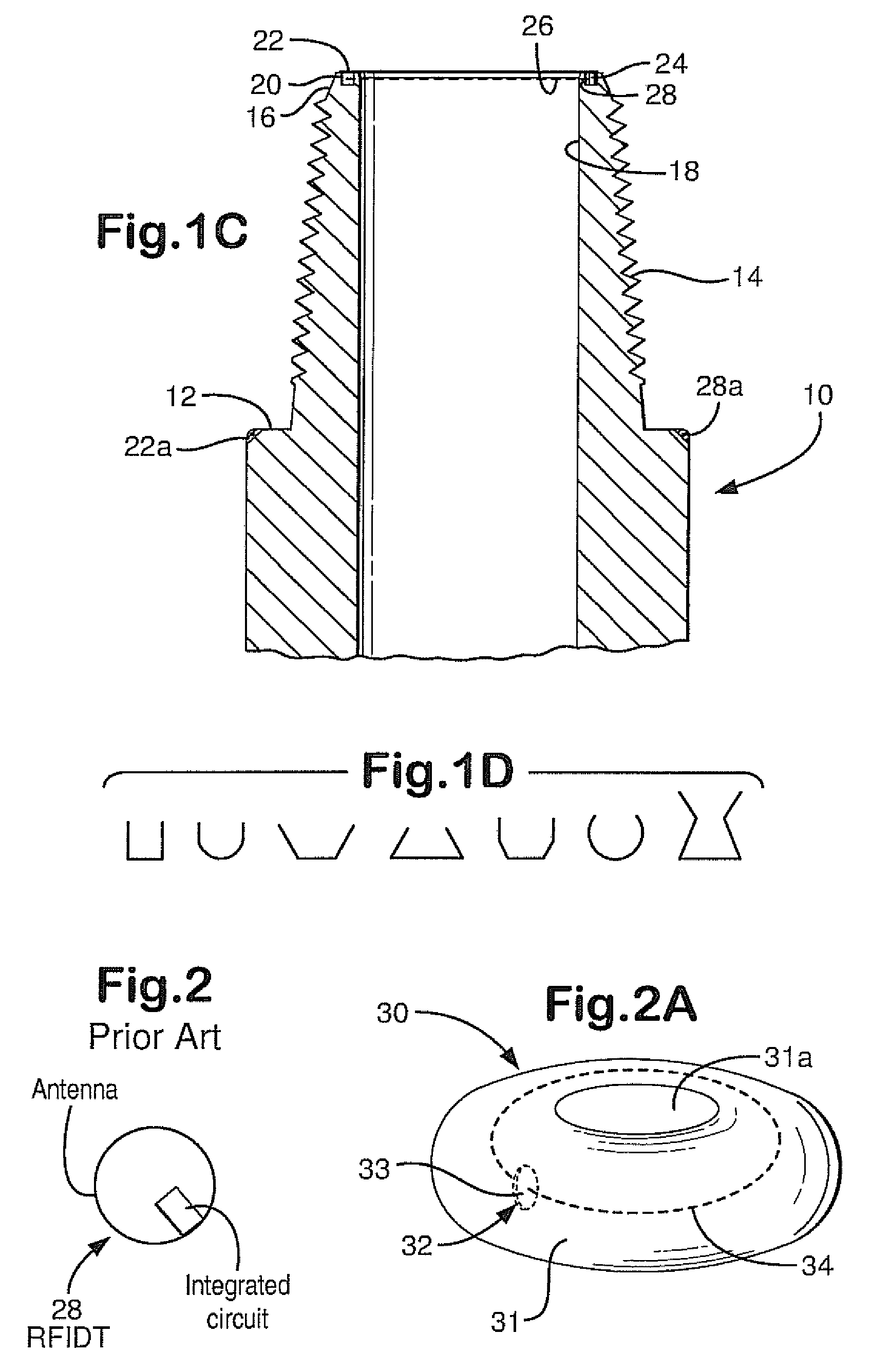
[0130]FIGS. 1A-1C show a pin end 10 of a drill pipe according to the present invention which has a sealing shoulder 12 and a threaded end portion 14. A typical flow channel 18 extends through the drill pipe from one end to the other. A recess 20 in the top 16 (as viewed in FIG. 1C) of the pin end 10 extends around the entire circumference of the top 16. This recess 20 is shown with a generally rectangular shape, but it is within the scope of this invention to provide a recess with any desired cross-sectional shape, including, but not limited to, the shapes shown in FIG. 1D. In one aspect an entire drill pipe piece with a pin end 10 is like the tubular shown in FIG. 3A or the drill pipe of FIG. 12B. The recess 20 (as is true for any recess of any embodiment disclosed herein) may be at any depth (as viewed in FIG. 1C) from the end of the pin end and, as shown in FIGS. 1A-1C may, according to the present invention, be located so that no thread is adjacent the recess.

[0131]It is within ...


PUM


Abstract

Generally, the subject matter disclosed herein is directed to devices and methods for energizing and detecting a wave-energizable apparatus on an item movable with respect to a working surface of a drilling rig. One illustrative device disclosed herein includes at least one mat adapted to be positioned on a working surface of a drilling rig and a plurality of spaced-apart energizing apparatuses operatively coupled to the at least one mat. Additionally, each of the plurality of spaced apart energizing apparatuses of the disclosed device is adapted to energize a wave-energizable apparatus attached to an item that is movable adjacent to the mat and relative to the working surface.

Description

CROSS REFERENCE TO RELATED APPLICATIONS[0001]This is a continuation-in-part of U.S. application Ser. No. 12 / 317,073 filed Dec. 18, 2008 now abandoned which is a division of U.S. application Ser. No. 11 / 255,160 filed Oct. 20, 2005 (issued as U.S. Pat. No. 7,484,625 on Feb. 3, 2009), which is a continuation in part of U.S. application Ser. No. 11 / 059,584 filed Feb. 16, 2005 (issued as U.S. Pat. No. 7,159,654 on Jan. 9, 2007) which is a continuation-in-part of U.S. application Ser. No. 10 / 825,590 filed Apr. 15, 2004 (abandoned)—from all of which the present invention and application claim the benefit of priority under the Patent Laws.BACKGROUND OF THE INVENTION[0002]1. Field of the Invention[0003]This invention is directed to systems and methods on wellbore operations rigs for identifying items; and, in certain aspects to identifying items on drilling rigs such as tubulars and drill pipe, using mat(s) with energizing apparatus and with wave-energizable apparatuses, e.g., radio frequenc...

Claims


Application Information

Patent Timeline
Patent Type & Authority Patents(United States)
IPC IPC(8): E21B47/09E21B47/02G01V3/18
CPCE21B15/00E21B17/006G06K19/0723E21B19/16E21B47/122E21B19/00E21B47/13
Inventor BLOOM, ROBERTELLISON, LEON D.KAMMANN, REINHOLDWORMS, MANFREDLAM, CLIVEMCCLUNG, III, GUY L.
Owner NAT OILWELL VARCO LP
Why Eureka
Try Eureka