
System and method for eliminating emissions from an air classification device

a technology of air classification device and air classification, which is applied in the direction of gas current separation, solid separation, sorting, etc., can solve the problems of inconvenient operation, and inability to remove airborne pollutants, so as to eliminate undesired emissions and eliminate emissions from the device

Inactive Publication Date: 2011-09-13
SCHENCK PROCESS LLC
View PDF10 Cites 10 Cited by
  • Summary
  • Abstract
  • Description
  • Claims
  • Application Information

AI Technical Summary

Benefits of technology

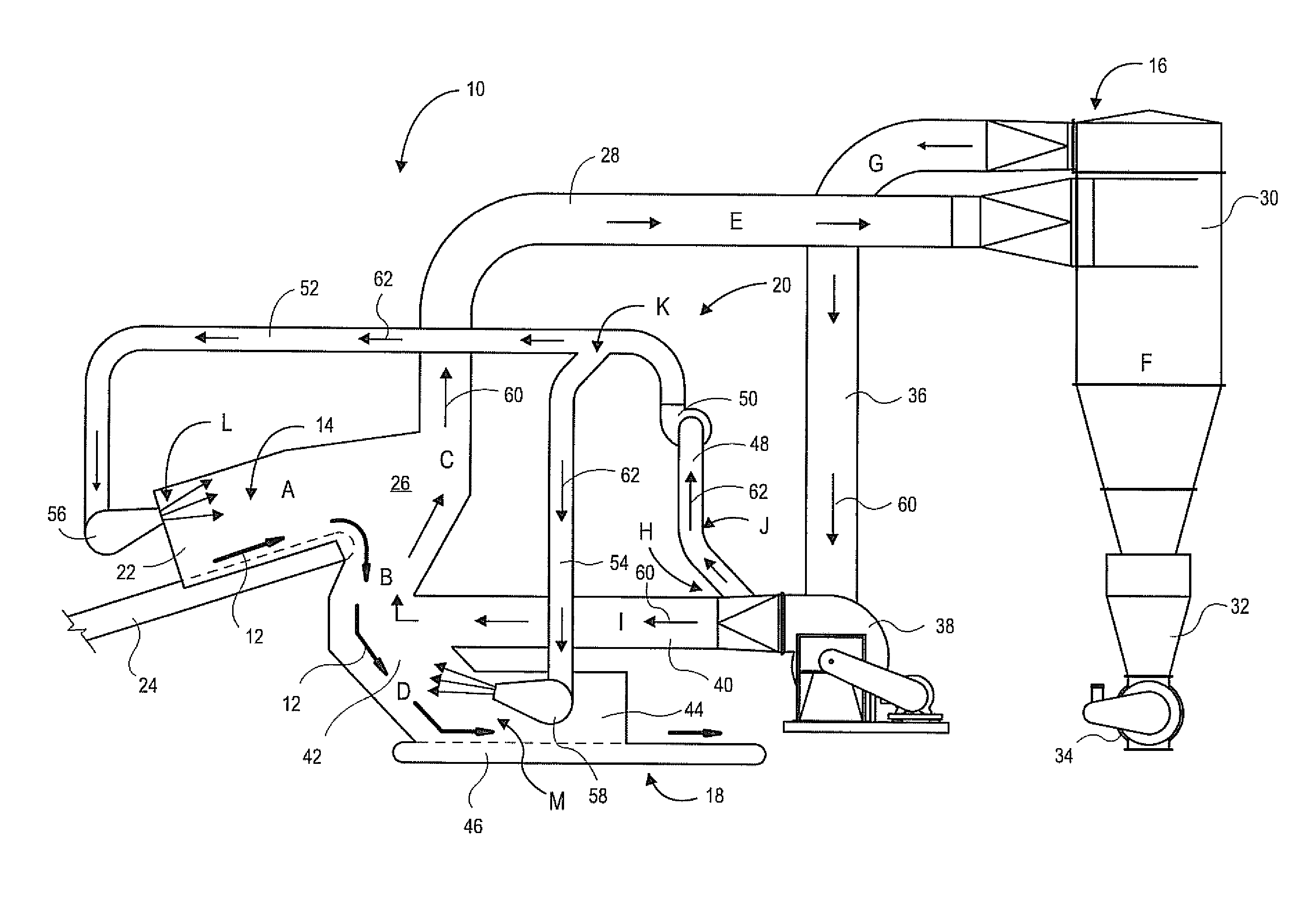
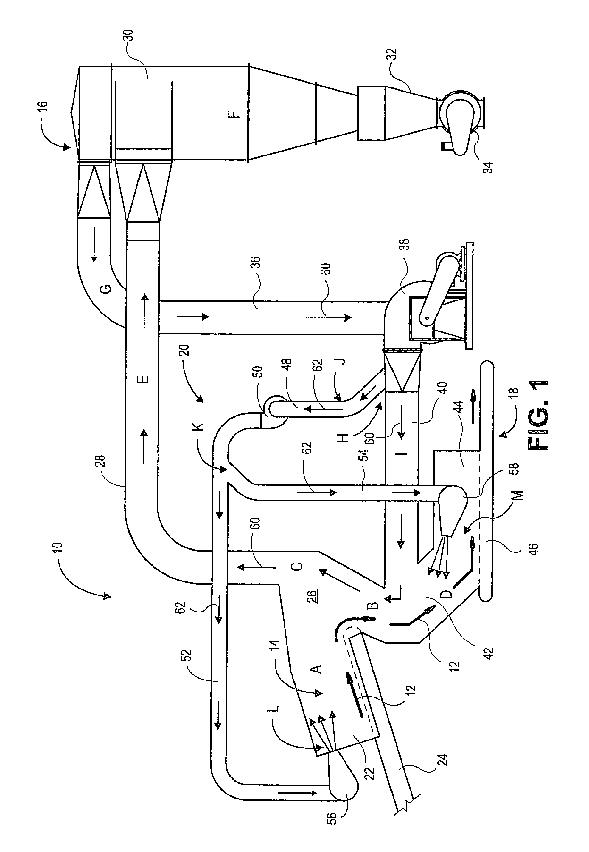
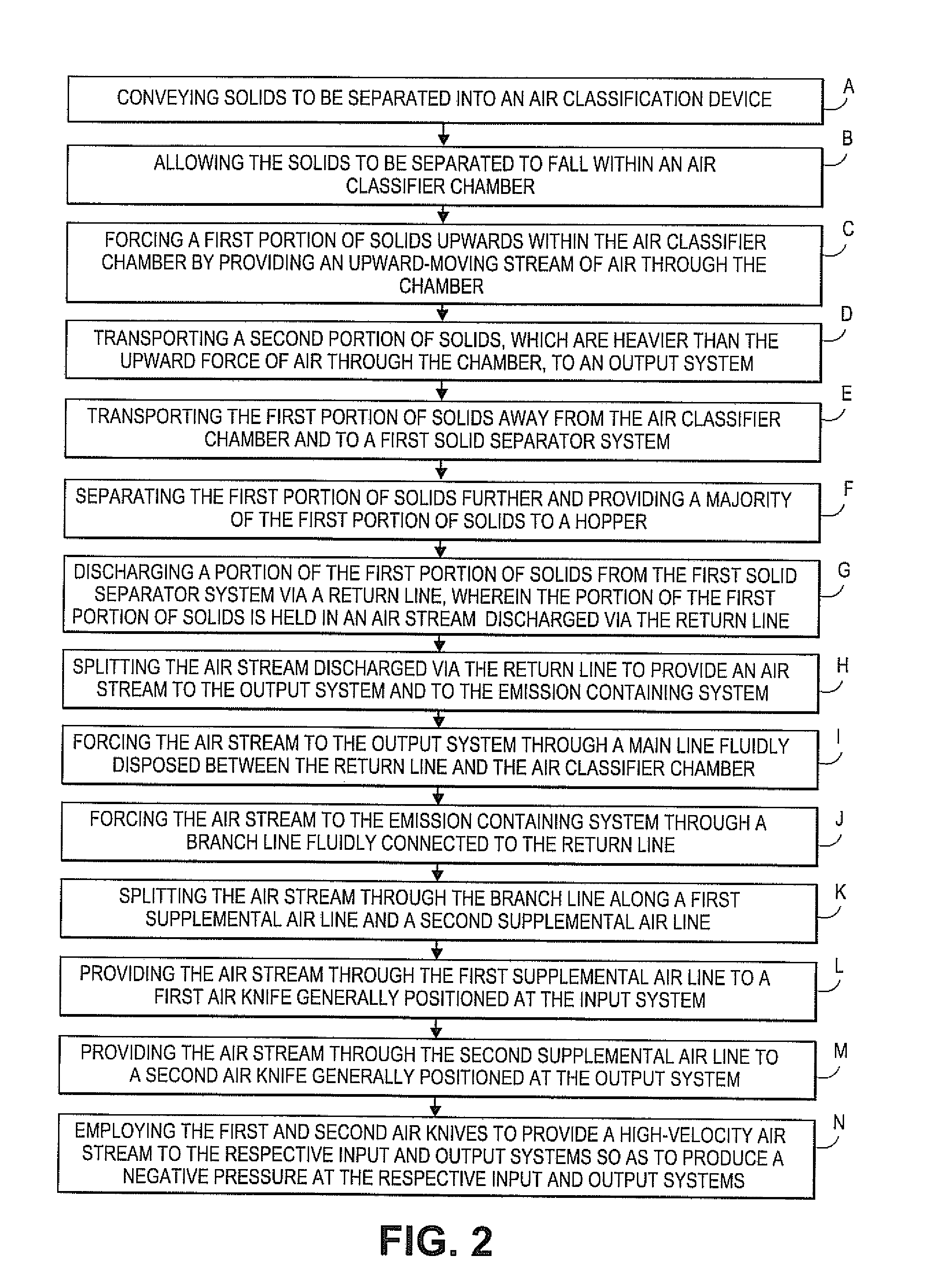
"The present invention provides a system and method for eliminating emissions from an air classification device. The system includes supplemental air lines and high-velocity air knives that create a negative air pressure at openings in the device to prevent polluted air from escaping. The device operates as a closed loop system, containing no emission point for polluted air. The technical effect of the invention is to significantly reduce air pollution and provide a safer workplace."

Problems solved by technology

Although an air classification device is theoretically a “closed loop” system, high velocity air currents inside the device can result in additional air, not required for the process, being drawn in at one point, such as an inlet, and escaping at another, such as an outlet.
The escaping air is commonly polluted, which results in undesired emissions at either or both of the inlet or outlet of the air classifier.
A disadvantage of bleeding off the air is that it will contain many airborne pollutants.
A disadvantage of using mechanical dampers to limit the area in which air can enter the air classifier is that the dampers are at least partially in the array of solids being fed into and out of the air classifier.
Additionally, the dampers are subject to physical damage from the varying solids transported in and out of the air classifier on in-feed and out-feed conveyors.
If one of the dampers becomes bent or broken, the damper becomes ineffective, and emissions will be allowed to escape from the air classifier, or the conveyors may become blocked, which results in unscheduled down time of the air classifier.
Additionally, the dampers require regular maintenance and repair.
Further, maintenance of the dampers is expensive.
Without proper maintenance, the dampers result in undesired emissions.
The dampers float over the solids and thus, provide a poor seal, such that emissions leak out of the spaces between the damper and the irregular shapes of the solids being conveyed.
Because it is undesirable to emit polluted air from the device at the inlet and outlet, it is necessary to contain the air inside the device.

Method used


Image

  • System and method for eliminating emissions from an air classification device
  • System and method for eliminating emissions from an air classification device
  • System and method for eliminating emissions from an air classification device

Examples


Embodiment Construction

[0021]The following detailed description of the invention references the accompanying drawings that illustrate specific embodiments in which the invention can be practiced. The embodiments are intended to describe aspects of the invention in sufficient detail to enable those skilled in the art to practice the invention. Other embodiments can be utilized and changes can be made without departing from the scope of the present invention. The following detailed description is, therefore, not to be taken in a limiting sense. The scope of the present invention is defined only by the appended claims, along with the full scope of equivalents to which such claims are entitled.

[0022]FIG. 1 illustrates an air classification device 10 for separation of solids 12 generally comprising an input system 14, a first solid separator system 16 (also referred to herein as a light solid separator system), an output system 18, and an emission containing system 20.

[0023]In embodiments of the present invent...


PUM


Abstract

An air classification device for separation of solids comprising an input system, a first solid separator system, an output system, and an emission containing system. The emission containing system employs supplemental air lines, a supplemental air source, and high-velocity air knives to create negative air pressure at any opening in the device. The negative air pressure induces air to move into the device and prevents polluted air from escaping the device at the openings.

Description

BACKGROUND[0001]1. Field[0002]Embodiments of the present invention relate to systems and methods for eliminating emissions from an air classification device. More particularly, embodiments of the present invention relate to an air classification device having a substantially closed loop system that prevents the emission of polluted air from the device.[0003]2. Related Art[0004]A well known system to separate solids is an air classification device, which employs an upward air stream to separate the solids by density, shape, and weight. Air classification devices are used in numerous applications, such as grain cleaning, de-dusting of plastic pellets, and separation of solids for recycling. For example, air classification devices are often used to separate solids resulting from the shredding of automobiles, household appliances, and other machinery comprising various different types of material.[0005]Air classification devices are a continuous process, wherein the solids to be separat...

Claims


Application Information

Patent Timeline
Patent Type & Authority Patents(United States)
IPC IPC(8): B07B7/00
CPCB07B4/02B07B4/08B07B9/02
Inventor ALTHOUSE, MICHAEL D.
Owner SCHENCK PROCESS LLC
Learn More