Digger sifter with ergonomic handle

a technology of ergonomic handle and sifter, which is applied in the direction of hand-operated machines/dredgers, solid separation, chemical equipment and processes, etc., can solve the problems of further hindering user's movements, and achieve the effect of being easily supported by the operator's clothing

Inactive Publication Date: 2011-09-13
BOLL CHARLES ARTHUR
View PDF22 Cites 16 Cited by
  • Summary
  • Abstract
  • Description
  • Claims
  • Application Information

AI Technical Summary

Benefits of technology

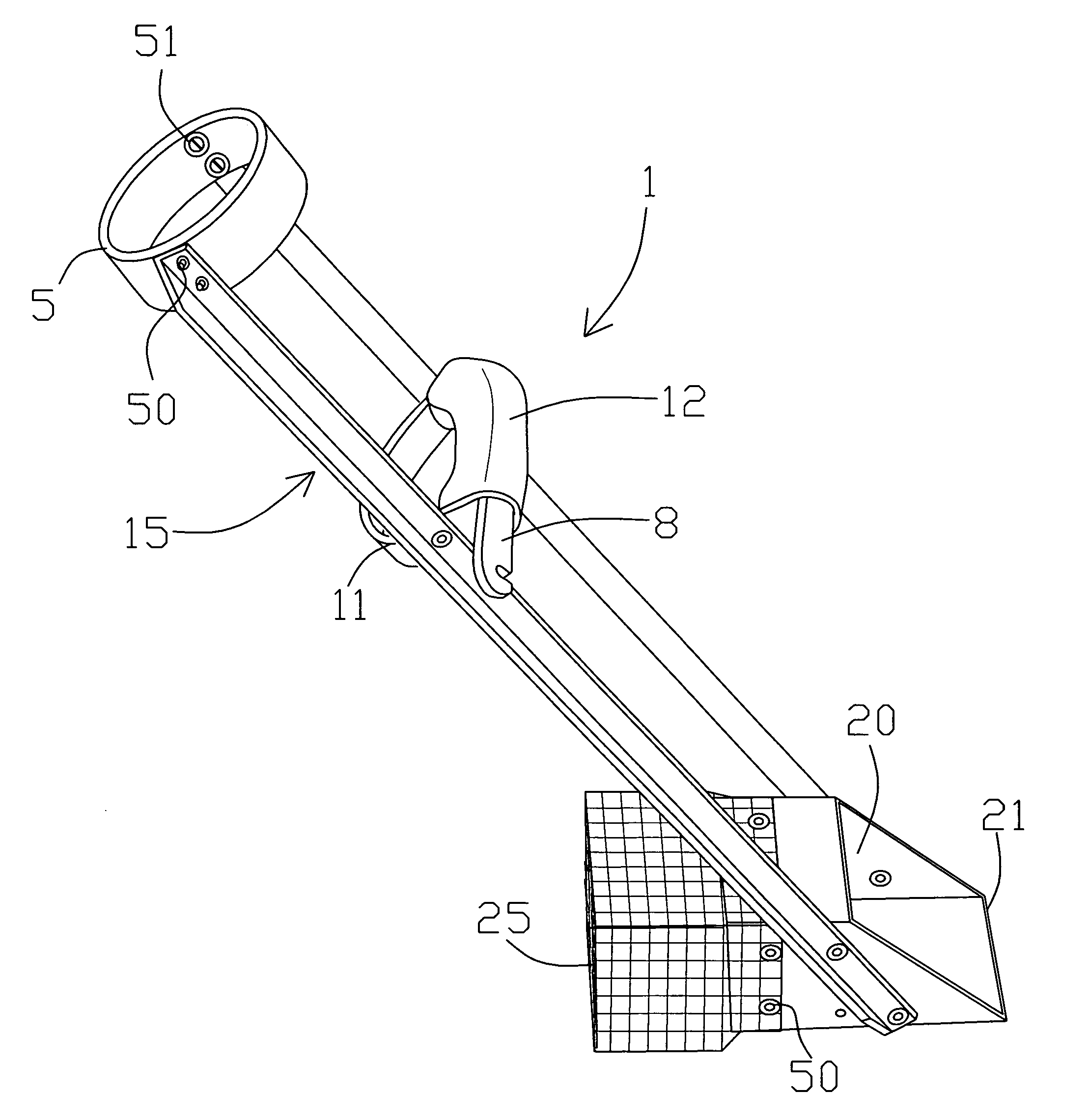
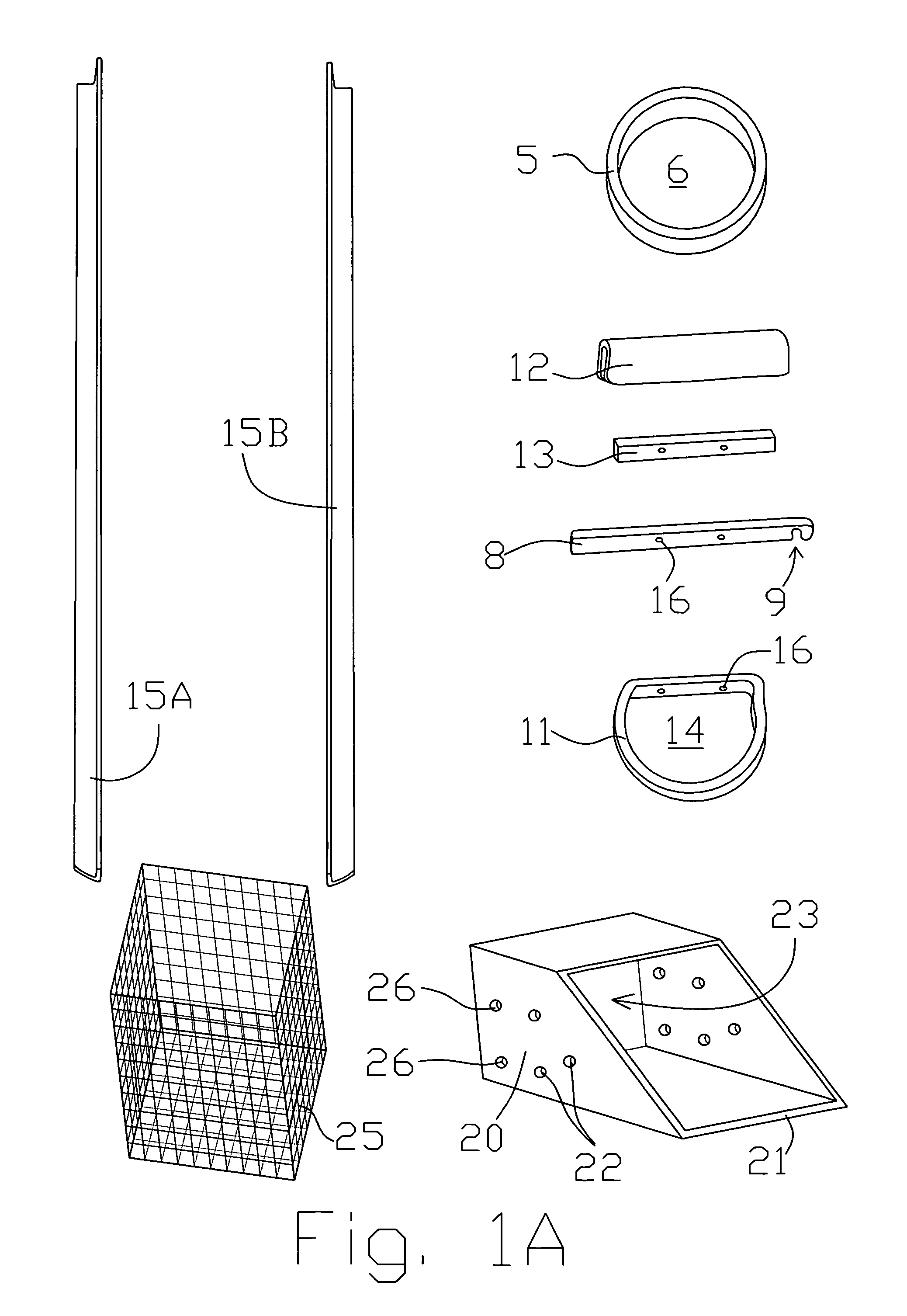
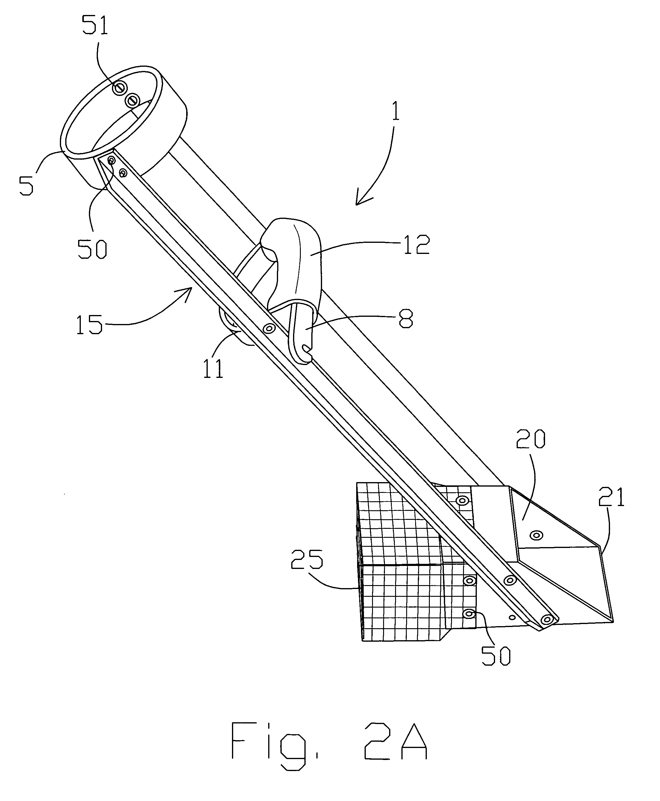
[0008]In one instance, the present digger sifter with ergonomic handle is easy on the wrist of the operator by means of two locations of body contact. That is, a user passes his arm through a ring or arm sleeve part 5 while gripping a handle 8 arranged horizontal to the ground whereas the prior art does not. The use of two body contacts produces a multiplier effect of by allowing the user to use a larger group of muscles which are stronger than those in the wrist. This effect creates a mechanical advantage that requires minimal movement of the operator's arm to operate the scoop member 20. A notch 9 is provided on arm 8 to keep the scoop sifter out of the magnetic field of the metal detector when carrying it or during detection operations. This allows the user to rest the arm muscles until it is used to scoop another object of interest. Two elongated arms provide a support structure for accepting a wide variety of scoops. The scoop 20 may comprise different materials and include various methods of attaching it to the elongated arm members. Bolts, rivets, various threaded shafts, nuts, washers, pins, or any other such fasteners may couple the scoop 20 to the elongated arms. Thus, the tool may be light in weight.
[0020]It is another object to provide a sorting and sifting device in which lateral and rotational stability between the operator and the scooping mechanism is provided to the device by a pair of transversely spaced-apart elongated arm members.

Problems solved by technology

The user's movements are further hindered by ocean waves which continually shift the sand from underneath the user's feet.

Method used


Image

  • Digger sifter with ergonomic handle
  • Digger sifter with ergonomic handle
  • Digger sifter with ergonomic handle

Examples


Embodiment Construction

[0036]The embodiments of the invention and the various features and advantageous details thereof are more fully explained with reference to the non-limiting embodiments and examples that are described and / or illustrated in the accompanying drawings and set forth in the following description. It should be noted that the features illustrated in the drawings are not necessarily drawn to scale, and the features of one embodiment may be employed with the other embodiments as the skilled artisan recognizes, even if not explicitly stated herein. Descriptions of well-known components and techniques may be omitted to avoid obscuring the invention. The examples used herein are intended merely to facilitate an understanding of ways in which the invention may be practiced and to further enable those skilled in the art to practice the invention. Accordingly, the examples and embodiments set forth herein should not be construed as limiting the scope of the invention, which is defined by the appen...


PUM


Abstract

A sifter device includes a proximal end having an arm support ring through which a user's hand and lower arm passes. A pair of elongated arms is arranged on opposite sides of the arm ring. A basket scoop, having a cutting edge, is arranged at a distal end of the device for scooping a medium that contains a detected metallic object that is retrieved. A grip is arranged along the pair of elongated member and includes an end that extends beyond the elongated members to be used in hanging the device from an article of clothing during metal detecting search activities when not digging or sifting in the medium. For example, an operator's belt or pants pocket may be used to hang the device from an article of clothing when not in use, preferably on the back pocket out of the way of the magnetic field generated by the metal detector.

Description

[0001]There are no related patent applications.[0002]The subject matter of the present invention did not receive federal government research and development funding.TECHNICAL FIELD[0003]The present invention generally relates to an apparatus, device for locating and separating objects from a medium in which such objects are disposed and for use in conjunction with a metal detector. In particular, the present invention relates to a device that allows a user to scoop and simultaneously sift a medium with one hand and forearm making it an ergonomic handle. Otherwise, the device may be hung from an article of clothing such as when not being used to sift through the medium.BACKGROUND OF THE INVENTION[0004]There is an increasing trend in the number of people becoming interested in amateur prospecting, treasuring hunting, metal detecting, amateur geology, and amateur archaeology. A metal detector may be used to pursue these various activities by identifying metallic objects arranged within...

Claims


Application Information

Patent Timeline
Patent Type & Authority Patents(United States)
IPC IPC(8): B07B1/49
CPCB07B1/02E02F3/02
Inventor BOLL, CHARLES ARTHUR
Owner BOLL CHARLES ARTHUR
Why Eureka
Try Eureka