High performance low noise rotorcraft blade aerodynamic design

a rotorcraft and low noise technology, applied in the field of helicopter systems, can solve the problems of blade stalling, no longer providing increasing lift, and too large angle of attack, and achieve the effect of less drag, higher lift, and higher li

Active Publication Date: 2011-09-13
BELL HELICOPTER TEXTRON INC
View PDF6 Cites 16 Cited by
  • Summary
  • Abstract
  • Description
  • Claims
  • Application Information

AI Technical Summary

Benefits of technology

[0012]One embodiment of the present invention is a main rotor helicopter blade with an aft cambered cross-section where a difference between a chord line of the cross-section and a camber line of the cross-section reaches a maximum between a midpoint of the chord line and the trailing edge of the cross-section. The difference between a chord line of the cross-section and a camber line of the cross-section increases from a leading edge of the cross-section to the maximum between a trailing edge of the cross-section and a midpoint of the chord line and decreases to the trailing edge producing the aft camber of the blade. The aft camber generates higher lift with less drag and delays stall at high Mach numbers.
[0013]Another embodiment of the present invention is a main rotor helicopter blade with an aft cambered cross-section where a difference between a chord line of the cross-section and a camber line of the cross-section reaches a maximum between a leading edge of the cross-section and a midpoint of the chord line. The difference between a chord line of the cross-section and a camber line of the cross-section increases from a leading edge of the cross-section to a maximum between the leading edge and a midpoint of the chord line and decreases to a trailing edge of the cross-section. The slope of the difference sequentially decreases from the leading edge to the maximum, increases negatively from the maximum, decreases negatively, and increases negatively to the trailing edge. The slope increases negatively from the maximum, decreases negatively, and increases negatively to the trailing edge to produce the aft camber of the blade. The aft camber generates higher lift with less drag and delays stall at high Mach numbers.
[0014]Another embodiment of the present invention is a main rotor helicopter blade with an aft cambered cross-section where a difference between a chord line of the cross-section and a camber line of the cross-section reaches a maximum between a leading edge of the cross-section and a midpoint of the chord line. The difference between a chord line of the cross-section and a camber line of the cross-section increases from a leading edge of the cross-section to a maximum between the leading edge and a midpoint of the chord line and decreases to a trailing edge of the cross-section. The slope of the difference sequentially decreases from the leading edge to the maximum, increases negatively from the maximum, decreases negatively, increases negatively, and decreases negatively to the trailing edge. The slope increases negatively from the maximum, decreases negatively, increases negatively, and decreases negatively to the trailing edge to produce the aft camber of the blade. The aft camber generates higher lift with less drag and delays stall at high Mach numbers.

Problems solved by technology

Since the airspeed experienced by a blade on the backward moving side is much less than the airspeed experienced on the forward side, the lift on the backward side is much less than the lift on the forward side, creating an imbalance.
At some point, the angle of attack is too great and the blade stalls.
When the blade stalls, it can no longer provide increasing lift.
Another limitation on the forward speed of a helicopter is drag.
If at the same time the lift of a backward moving blade of main rotor of helicopter is increased the drag is also increased significantly, the speed available due to the increased lift will be limited by the corresponding drag.
As a helicopter blade reaches high Mach numbers, the blade begins to stall.
The stalling of the blade, again, limits the forward speed the helicopter can achieve.

Method used


Image

  • High performance low noise rotorcraft blade aerodynamic design
  • High performance low noise rotorcraft blade aerodynamic design
  • High performance low noise rotorcraft blade aerodynamic design

Examples


Embodiment Construction

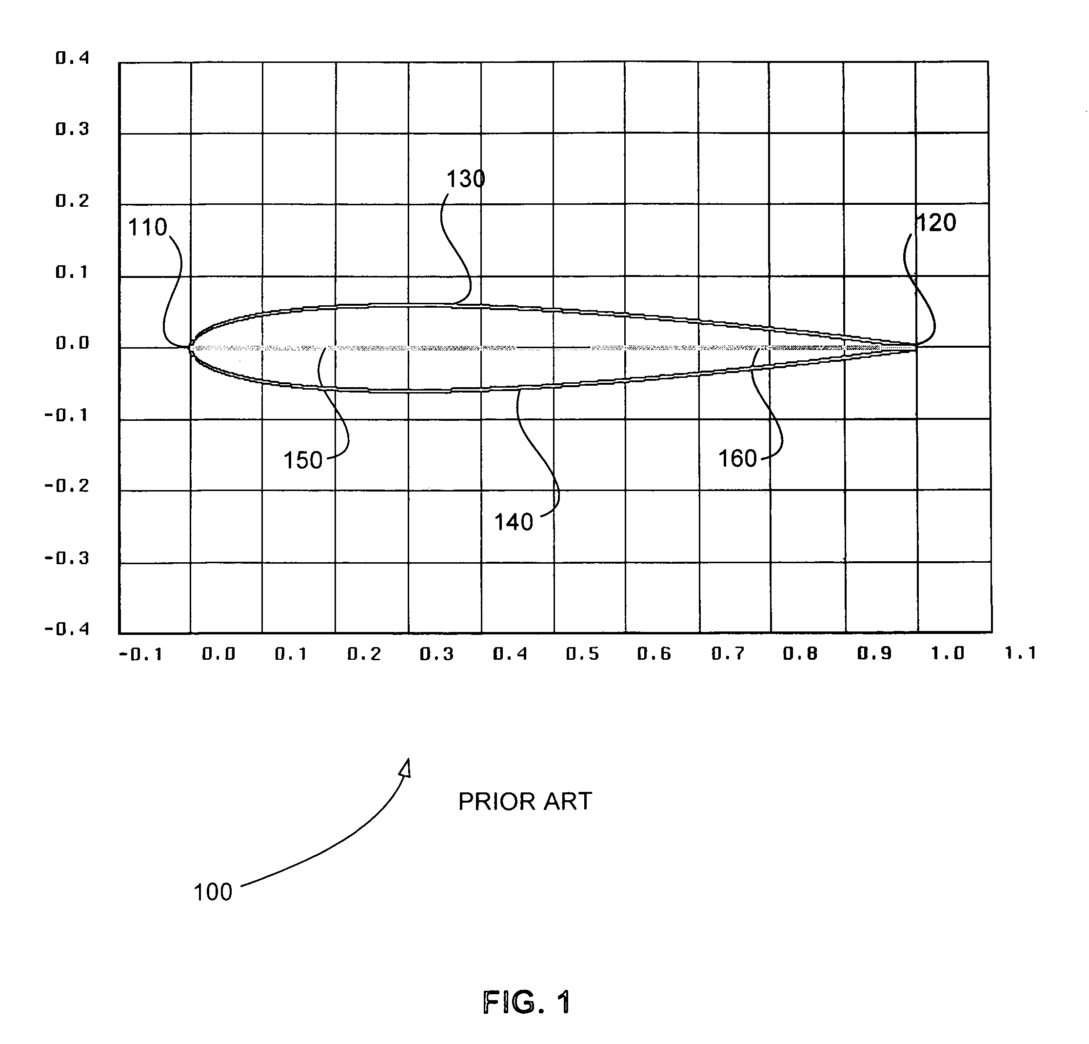
[0053]FIG. 1 is a schematic diagram of an exemplary cross-section 100 of a main rotor blade of a helicopter where there is no difference between chord line 150 and camber line 160. The vertical axis represents a thickness and the horizontal axis represents a depth of cross-section 100. Cross-section 100 includes leading edge 110, trailing edge 120, upper surface 130, lower surface 140, chord line 150, and camber line 160. Chord line 150 is defined as the middle of trailing edge 120 to farthest point on leading edge 110. The middle of a trailing edge is used because blades do not usually end in a single point. A trailing edge that has a rounded or blunt trailing edge is easier to manufacture and maintain.

[0054]Camber line 160 is defined as the collection of midpoints of lines drawn from upper surface 130 to lower surface 140 and perpendicular to chord line 150. Since upper surface 130 and lower surface 140 are mirror images, chord line 150 and camber 160 are the same line for cross-s...


PUM

PropertyMeasurementUnit
Mach numbersaaaaaaaaaa
timeaaaaaaaaaa
air speedaaaaaaaaaa

Abstract

One embodiment of the present invention is a main rotor helicopter blade for generating higher lift with less drag and delaying stall at high Mach numbers. A cross-section of this blade includes aft camber. The difference between a chord line of the cross-section and a camber line of the cross-section increases from a leading edge of the cross-section to a maximum between a trailing edge of the cross-section and a midpoint of the chord line and decreases to the trailing edge producing the aft camber of the blade. The aft camber generates higher lift with less drag and delays stall at high Mach numbers.

Description

BACKGROUND OF THE INVENTION[0001]1. Field of the Invention[0002]Embodiments of the present invention relate to helicopter systems and methods that enable a blade of a rotor of a helicopter to generate higher lift with less drag and to delay stall at high Mach numbers. More particularly, embodiments of the present invention relate to main rotor helicopter blades, helicopter systems, and methods for designing helicopter blades that include or create aft camber, which generates higher lift with less drag and delays stall at high Mach numbers.[0003]2. Background Information[0004]In horizontal flight, a blade of the main rotor of a helicopter acts as a moving airfoil or wing. Unlike the wing of an airplane, however, the main rotor blade of a helicopter is periodically moving in the direction of movement of the helicopter and periodically moving in a direction opposite to the direction of movement of the helicopter. Therefore, a main rotor blade of a helicopter experiences two vastly diff...

Claims


Application Information

Patent Timeline
Patent Type & Authority Patents(United States)
IPC IPC(8): B64C27/467
CPCB64C27/467Y10T29/49332Y10S416/02B64C11/16B64C11/18B64C27/46
Inventor AGNIHOTRI, ASHOK K.NARRAMORE, JIMMY CHARLESSCHILLINGS, JOHN J.
Owner BELL HELICOPTER TEXTRON INC
Why Eureka
Try Eureka