Switch

a technology of switch and switch body, applied in the field of switch, can solve the problems of increasing assembly man-hour, inability to realize compact switch, increasing cost, etc., and achieve the effect of stable operation characteristi

Inactive Publication Date: 2011-09-13
ORMON CORP
View PDF3 Cites 10 Cited by
  • Summary
  • Abstract
  • Description
  • Claims
  • Application Information

AI Technical Summary

Benefits of technology

[0009]According to the first aspect of the invention, the plunger is reciprocally moved to open and close the contact by one coil spring, so that the number of components and the assembly man-hour can be decreased to achieve the cost reduction. Additionally, the movable contact piece is instantaneously reversed by a spring force of the coil spring, and the opening and closing speed of the contact is significantly enhanced, which eliminates the need of using the contact having the large contact area. Therefore, the switch can be miniaturized.
[0016]In the switch according to the first and third aspects of the invention, preferably a forced disjunction pawl portion is provided in one end portion of the spring, the forced disjunction pawl portion being latched in an edge portion of the other end portion of the movable contact piece to perform forced disjunction between the fixed contact and the movable contact. Accordingly, the contact welding is forcedly solved to suppress the malfunction, so that high-reliability switch can be obtained.
[0018]In the switch according to the first to fourth aspects of the invention, preferably a position regulating projected strip is projected from an inside surface of the housing fitted in the base, the position regulating projected strip being latched in an upper surface edge portion of the movable contact piece to regulate a position during return. Accordingly, the position of the movable contact piece is regulated by the position regulating projected strip, so that the dropout can be prevented to obtain the switch having a stable operation characteristic.

Problems solved by technology

Therefore, the number of components and assembly man-hour are increased to lead to cost increase.
As a result, a contact having a large contact area is required to prevent contact wear in opening and closing the large-current contact, and disadvantageously the compact switch cannot be realized.

Method used


Image

  • Switch
  • Switch
  • Switch

Examples


first embodiment

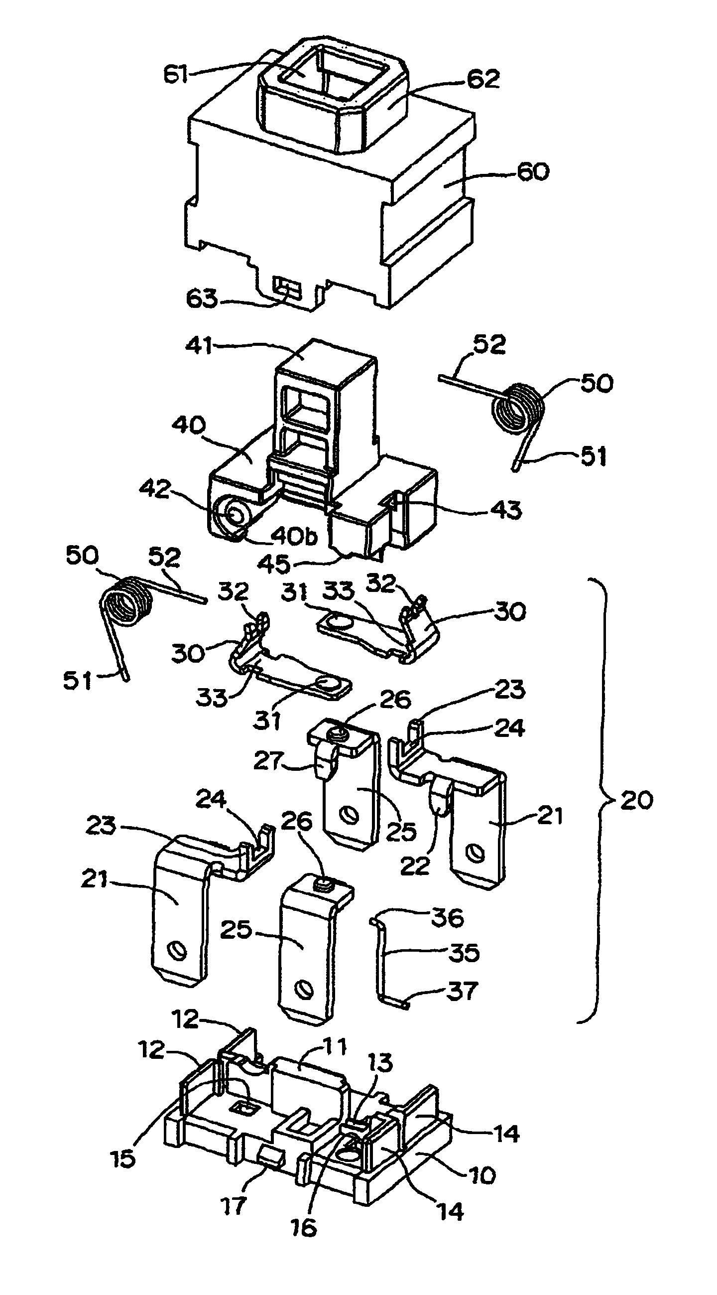
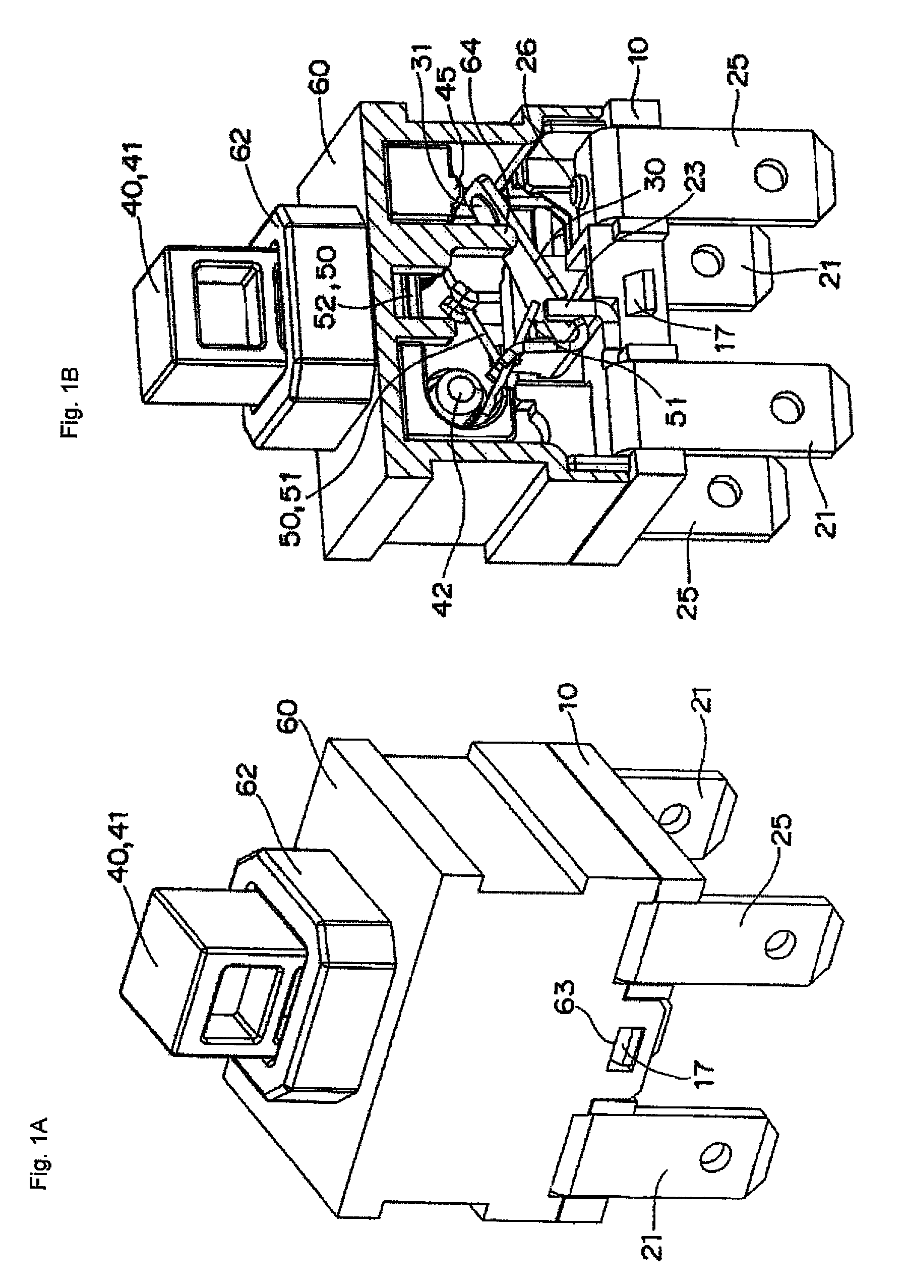
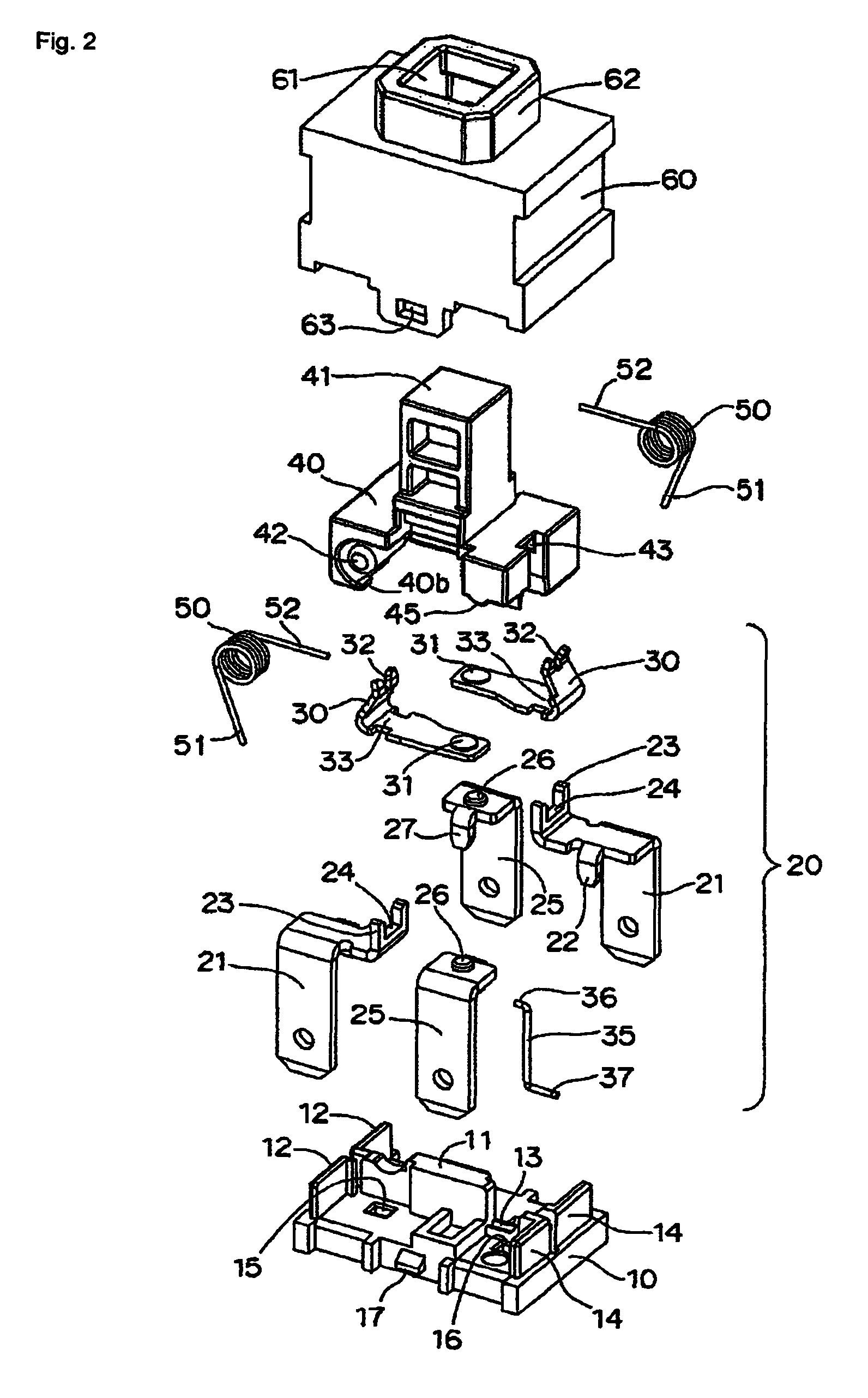
[0046]Preferred embodiments of the invention will be described below with reference to the accompanying drawings. Referring to FIGS. 1 to 8, a switch according to the invention includes a base 10, two sets of contact mechanisms 20 and 20, a plunger 40, and a housing 60. The two sets of contact mechanisms 20 and 20 are assembled into the base 10. The plunger 40 includes a pair of coil springs 50 and 50 and a lock pin 35, and the plunger 40 works the contact mechanism 20. The housing 60 is fitted in the base 10 to cover the contact mechanism 20 therewith, and the housing 60 supports the plunger 40 while the plunger 40 can vertically be moved.

[0047]Referring to FIG. 2, in the base 10, a pair of insulating walls 12 and 12 is projected on the same straight line from one end portion side of a partition 11 projected in the center of an upper surface of the base 10, an engagement groove 13 is provided on an extended line on the other end portion side, and a pair of insulating walls 14 and 1...

fourth embodiment

[0066]That is, as shown in FIGS. 13 to 16, the switch of the fourth embodiment includes the base 10, the two sets of contact mechanisms 20 and 20, the plunger 40, and the housing 60. The two sets of contact mechanisms 20 and 20 are assembled into the base 10. The plunger 40 includes the pair of coil springs 50 and 50 and the lock pin 35, and the plunger 40 works the contact mechanism 20. The housing 60 is fitted in the base 10 to cover the contact mechanism 20 therewith, and the housing 60 supports the plunger 40 while the plunger 40 can vertically be moved.

[0067]Referring to FIG. 14, in the base 10, the pair of insulating walls 12 and 12 is projected on the same straight line from one end portion side of the partition 11 projected in the center of the upper surface of the base 10, the engagement groove 13 is provided on the extended line on the other end portion side, and the pair of insulating walls 14 and 14 is projected on the same straight line from the other end portion side o...


PUM


Abstract

A switch includes a base, a support terminal assembled in the base, a movable contact piece made of a belt-like electroconductive material bent into a substantial J-shape in section, a plunger vertically movably accommodated in an internal space, and a coil spring turnably supported by the plunger. The movable contact piece includes a movable contact provided in one end portion thereof. An intermediate portion of the movable contact piece is turnably supported by a turning support portion of the support terminal. The internal space is formed by fitting a housing in the base. The plunger is slid while vertically moved press-contact one end portion of the coil spring against the other end edge portion of the movable contact piece such that the movable contact piece is reversed to bring the movable contact into contact with a fixed contact or to separate the movable contact from the fixed contact.

Description

BACKGROUND OF THE INVENTION[0001]1. Field of the Invention[0002]The present invention relates to a switch and, in particular, to a switch in which a contact can be opened and closed by a pressing working.[0003]2. Description of the Related Art[0004]Conventionally, for example, Japanese Patent Application Laid-Open No. 10-208581 discloses a switch structure of the switch in which the contact can be opened and closed by the pressing working.[0005]In the switch structure disclosed in Japanese Patent Application Laid-Open No. 10-208581, a movable terminal 37 is reciprocally moved in a vertical direction by working a button 14, and movable contacts 41 and 41 disposed in end portions of the movable terminal 37 is brought into contact with and separated from facing fixed contacts 45 and 45 respectively.[0006]However, in the switch structure disclosed in Japanese Patent Application Laid-Open No. 10-208581, it is necessary that the movable terminal 37 be supported by a retention spring 46 an...

Claims


Application Information

Patent Timeline
Patent Type & Authority Patents(United States)
IPC IPC(8): H01H13/14
CPCH01H13/30H01H3/001H01H5/16H01H13/562
Inventor KIYONO, YASUHIRONARUO, TOSHIHIRO
Owner ORMON CORP
Why Eureka
Try Eureka