Apparatus for tracking a moving light source

a technology for moving light sources and apparatuses, applied in the field of tracking devices, can solve the problems of a large number of components, a large number of mechanical components, and a limited scope of devices that rotate about only one or two axes, so as to facilitate tracking a target, reduce assembly and maintenance, and reduce the complexity of mechanical components

Active Publication Date: 2011-09-13
MOSER MARK K
View PDF4 Cites 15 Cited by
  • Summary
  • Abstract
  • Description
  • Claims
  • Application Information

AI Technical Summary

Benefits of technology

[0011]A main sensor (the master sensor) is positioned in an elongated recess which extends along parallel to the sight axis so that when it detects incident sunlight, it indicates that all three sector sensors are detecting incident sunlight simultaneously. At this instant the payload or solar conversion device is also facing the sun in a position normal to the sight axis. Each linear actuator has a similar relationship to its source pair. The controller reacts instantly to the signals sent by the control sensors for extending or retracting the linear actuators. An “all stop” circuit senses this state and stops all linear actuators until the sun moves to a position at which a primary sensor no longer detects it then, the process is repeated to maximize the amount of time during the sun's availability in which the payload sights the source by being positioned in a plane perpendicular to the sight axis of the carrier platform.
[0021]With a simple setup procedure, relatively low cost purchase, the return on investment will be significantly increased beyond a lesser efficient and more expensive solar tracking device. As a solar tracking device, it will find immediate use anywhere on earth, particularly in the higher latitudes. Additionally, as a low maintenance device, it will need no seasonal alignment with the position of the sun at any given time. In regions of snow and ice, the sensor array module can be displaced to any height above the tracking platform to ensure it is always able to acquire the sun.

Problems solved by technology

However, a problem lies in the capability of such devices to track the sun continuously in all locations of interest and possible use, and under varying external conditions, such as weather.
However, devices that rotate about only one or two axes, are limited in scope.
These systems also tend to have a significantly complex or heavy frame and support structure with a multitude of components.
A large tracker with significant mass will take more time to orient than a small light tracker.
Consequently, the reorientation of the tracker will generally take only a few seconds.

Method used


Image

  • Apparatus for tracking a moving light source
  • Apparatus for tracking a moving light source
  • Apparatus for tracking a moving light source

Examples


Embodiment Construction

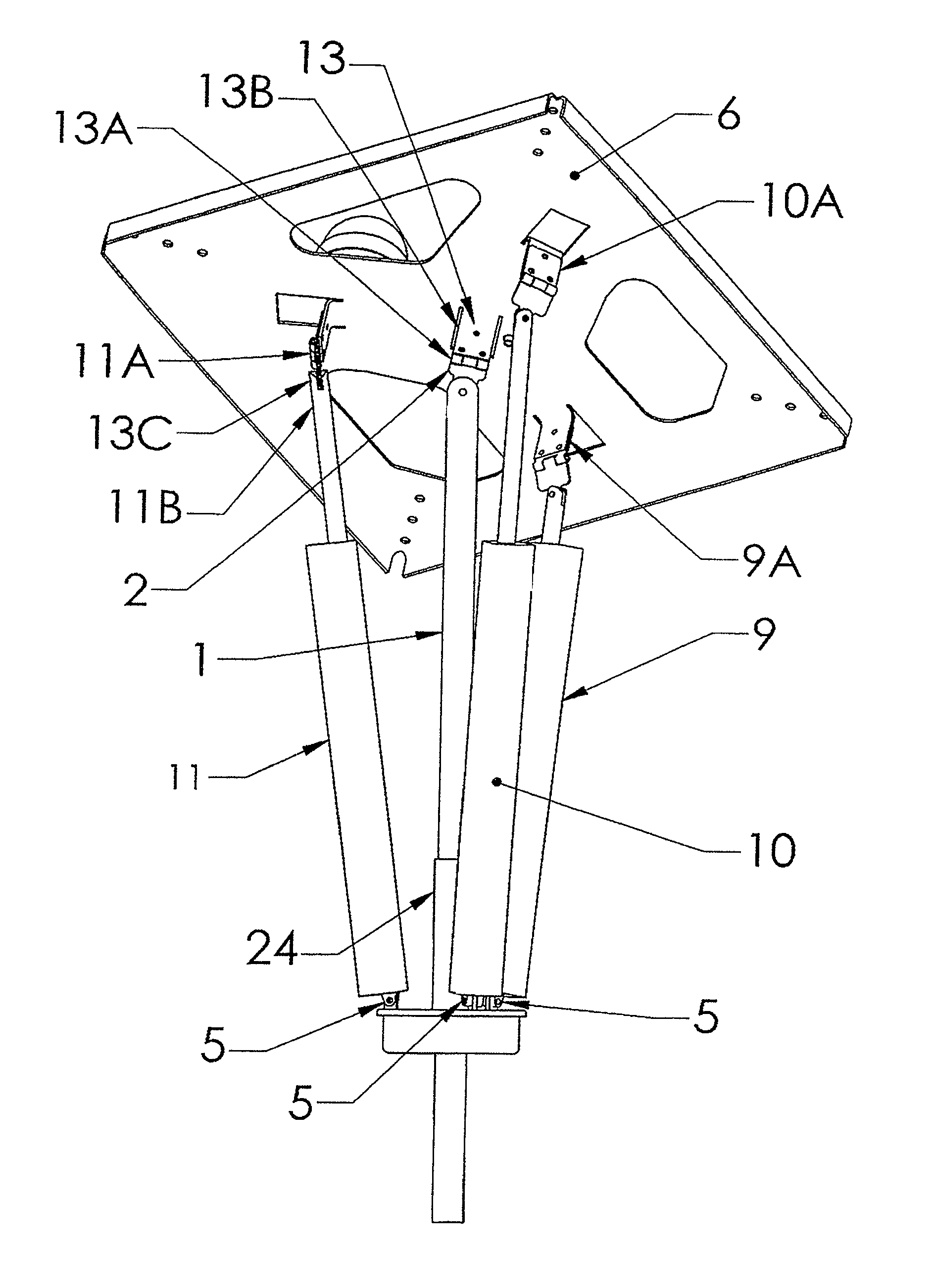
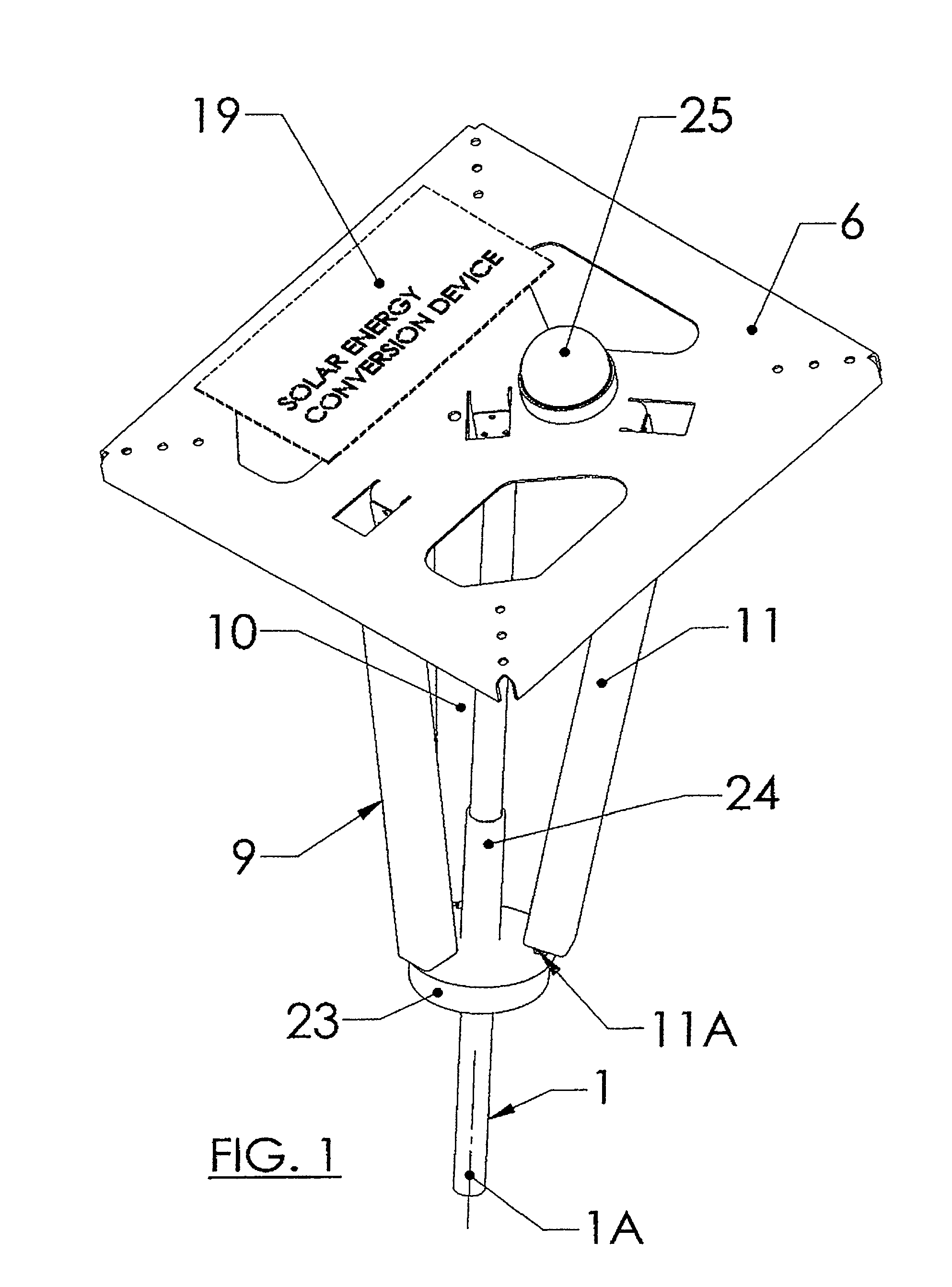
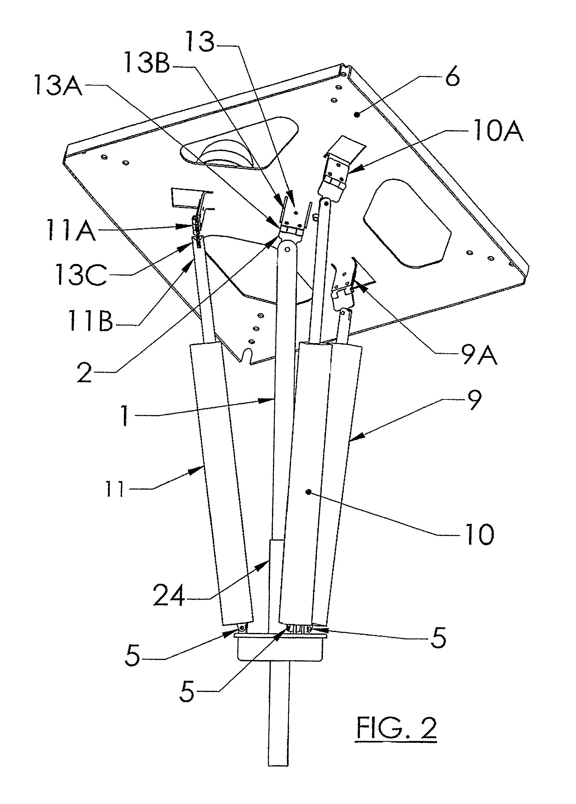
[0036]The system shown and described is able to track the target light source within a solid angle of approximately 5.2 steradians, that is, about 10 degrees up from the horizon in a full 360 degrees. Consequently, it can be used as a solar detector at almost any latitude on earth. As a solar panel tracker, the instant system can be used from the earthly poles in their respective summers to the Equator. Once the tracker has been installed with the payload device, only power needs to be supplied. The integrated sensor / actuator controls will power up and orient the device to the direction of the target.

[0037]Referring to FIGS. 1 and 2, the device comprises a multiaxial mechanical system including three linear actuators 9, 10, and 11. Each actuator extends and retracts linearly and has a base end (11A for actuator 11, FIG. 2), and a rod end 11B. A single support column 1 supports the entire device. The support column 1 may be mounted to a stand (portable) or permanently fixed, as in co...


PUM


Abstract

A tracking device for automatically following a moving light source that is detectable in the presence of ambient light. A carrier platform including one or more radiant energy conversion devices and a sensor array is mounted to an upright support column with a universal joint. Three independently-operated, linear actuators are equally angularly spaced about the support column with an upper end connected to the carrier platform with a universal hinge and a lower end connected to a floating base with a spherical hinge. A sensor array carried by the carrier platform includes a primary sensor associated with each actuator. During operation, when a primary sensor is not receiving direct radiant energy, the actuator retracts, and when it is receiving radiant energy directly, the actuator extends. The result is that the platform will directly track the sun across the horizon.

Description

RELATED APPLICATION[0001]This application claims priority of U.S. Provisional Application No. 60 / 013,003 entitled “POINT LIGHT TRACKER” filed Dec. 12, 2007.FIELD OF THE INVENTION[0002]The present invention relates to tracking devices, and more particularly, it relates to devices that automatically maintain a specific orientation to a light source. The present invention is described in the context of a solar tracker although the physical structure and associated electronic control circuit have a broader application than solar tracking devices. As used herein, a “light source” or “point light source” refers to a source of light which emits radiant energy which is detectably greater in intensity than is ambient light. Ambient light is all incident light at a location, particularly all reflected light.BACKGROUND OF THE INVENTION[0003]In the current environment of significant human power needs, solar energy will necessarily provide a significant contribution. One such need is a requireme...

Claims


Application Information

Patent Timeline
Patent Type & Authority Patents(United States)
IPC IPC(8): G01C21/02F24J2/38H01L31/042F24S50/20
CPCF24J2/38F24J2/5232F24J2/5267F24J2/5431G01S3/7862F24J2/5417Y02E10/47F24J2002/5441F24S30/48F24S50/20F24S2030/115F24S25/12F24S30/45F24S20/70F24S30/20
Inventor MOSER, MARK KEVIN
Owner MOSER MARK K
Why Eureka
Try Eureka