Positioning system and method

a technology of positioning system and position system, applied in the field of positioning system, can solve the problems of limiting the effectiveness of employed technologies, the location of personnel and equipment within, and the problem of not being solved

Active Publication Date: 2011-09-13
RAYTHEON CO
View PDF17 Cites 24 Cited by
  • Summary
  • Abstract
  • Description
  • Claims
  • Application Information

AI Technical Summary

Benefits of technology

[0007]Development of the positioning system can provide individuals and equipment moving within a space, either above or below ground, the capability to know their location in three dimensions. The positioning system finds the location of an object by applying theoretical calculations, scale model testing, and technology demonstrations including state-of-the-art signal processing, fusion of multiple sensor data, and unique concepts of operation.
[0009]A premise of an exemplary embodiment of the positioning system is to use multiple transmitters on the surface, in the vicinity of an underground space, to provide magnetic beacons. The signal processing can be supplemented with distant signals of opportunity, both cooperative such as the High frequency Active Auroral Research Program (HAARP) and uncooperative such as very low frequency and low frequency navigation / communications systems and AM radio signals. The software defined radio receiver carried underground can accurately measure the angles between the various transmitters (vectors pointing back along magnetic field lines to the surface beacons). Given that the surface transmitter locations can be accurately determined when deployed and the magnetic radiation field can be calculated, the underground receiver location can be determined. This software defined radio receiver and associated processing unit are compatible with existing land navigation systems to provide a handheld capability that functions both above and below ground level.
[0011]The positioning system provides navigation and survey both above and below ground and can be used in varying geologies. In addition to the underground application, the positioning system has applicability to the robust surface navigation problem.

Problems solved by technology

Yet when conventional techniques are employed in an underground environment, geo-location has proven a challenge that drives concepts of operations to bootstrap techniques to geo-locate instrumentation and geological contacts and can actually limit the effectiveness of employed technologies.
However, a longstanding problem exists with determining location of personnel and equipment within, for example, underground facilities without the use of surveying.
To date, this problem has not been resolved because of the difficulty of signaling / communicating between the Earth's surface and underground facilities / caverns / mines and the complexity of electromagnetic propagation within the Earth.

Method used


Image

  • Positioning system and method
  • Positioning system and method
  • Positioning system and method

Examples


Embodiment Construction

[0021]In the following detailed description, reference is made to the accompanying drawings, which form a part hereof and show by way of illustration specific embodiments in which the invention may be practiced. These embodiments are described in sufficient detail to enable those skilled in the art to practice the invention, and it is to be understood that other embodiments may be utilized, and that structural, logical, and other changes may be made without departing from the spirit and scope of the present invention. The progression of processing steps described is exemplary of embodiments of the invention; however, the sequence of steps is not limited to that set forth herein and may be changed as known in the art, with the exception of steps necessarily occurring in a certain order.

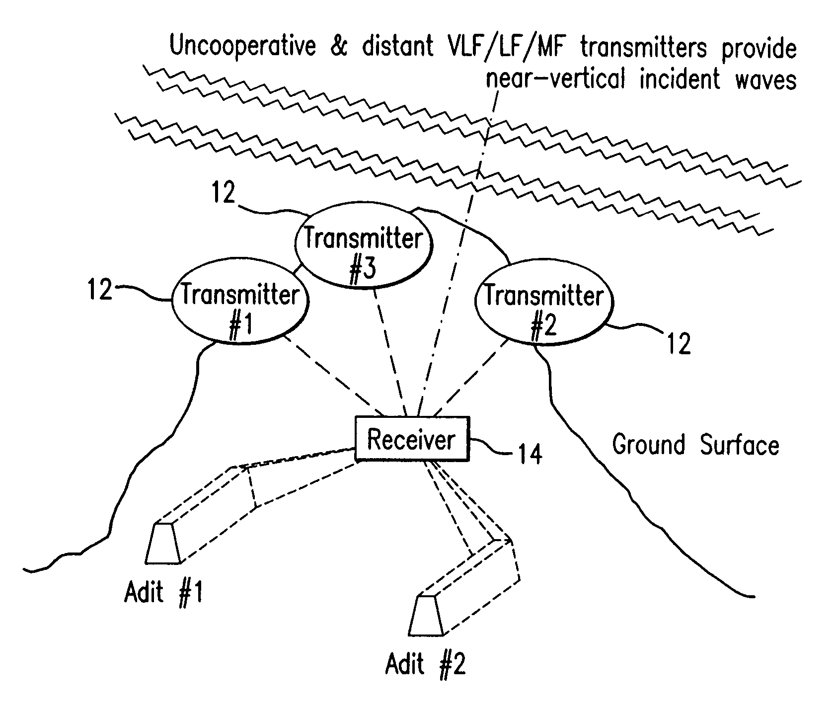
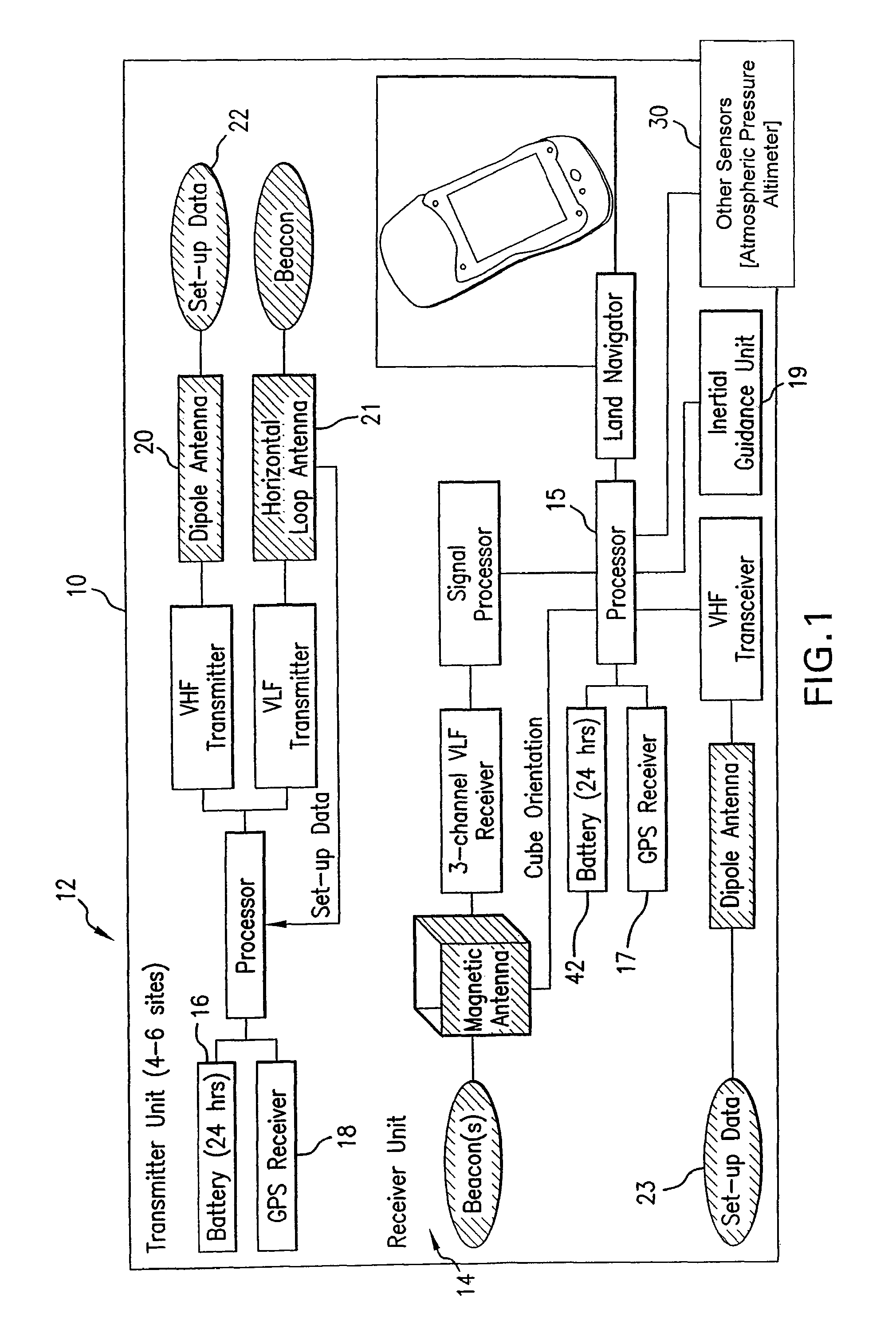
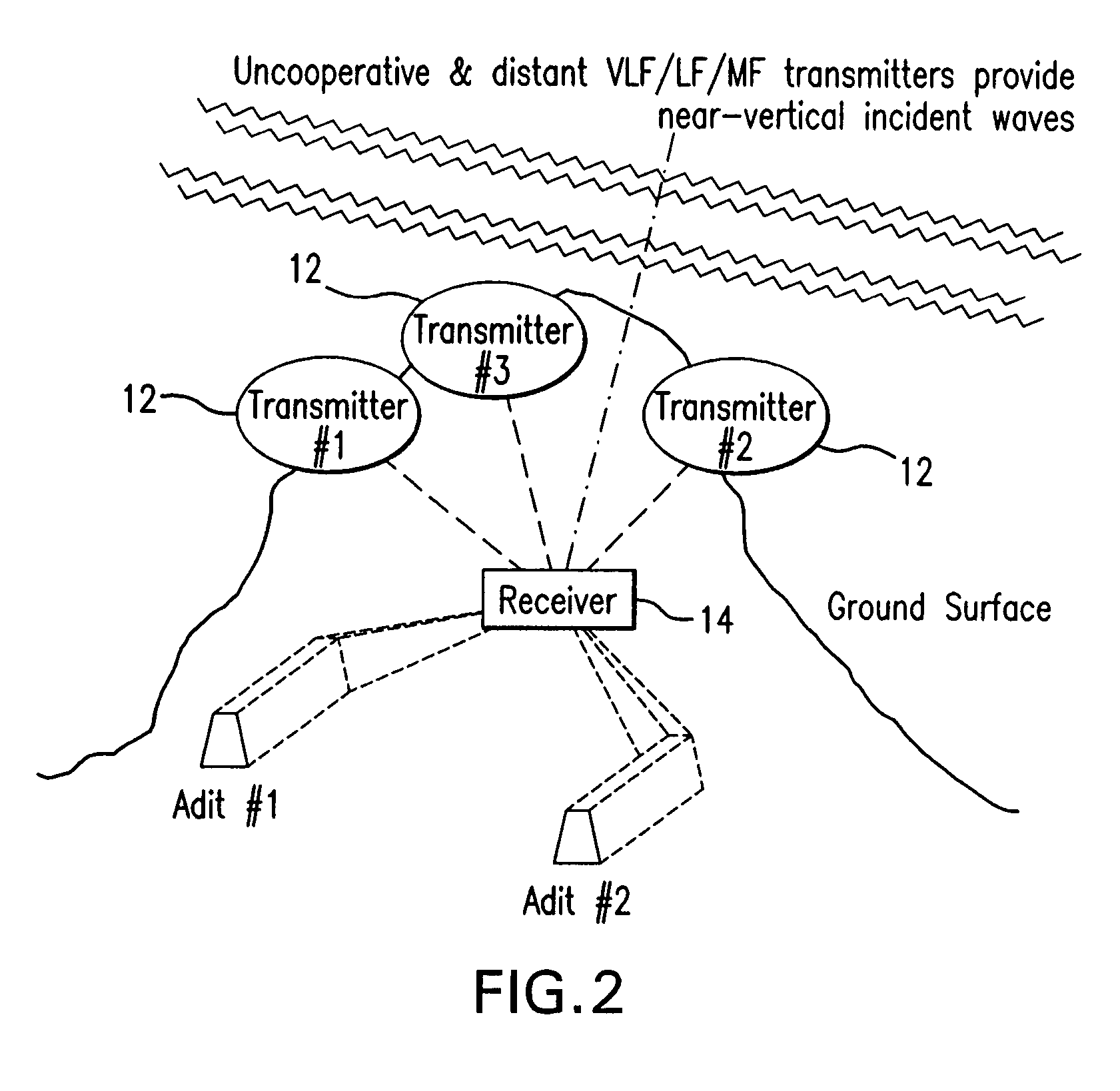
[0022]An exemplary positioning system 10 is shown in FIG. 1. The positioning system has transmitter sites 12 and a receiver unit 14. As shown in FIG. 1, the positioning system 10 entails the design and...


PUM


Abstract

A positioning system designed to provide a three dimensional location of an object. The system can include one or more multiple transmitters or electromagnetic beacons, software defined radio receivers with an associated processing unit and data acquisition system, and magnetic antennas. The system applies theoretical calculations, scale model testing, signal processing, and sensor data to operate.

Description

[0001]This application claims the benefit of U.S. Provisional Application Ser. No. 60 / 750,787, filed on Dec. 16, 2005, the entire disclosure of which is incorporated herein by reference.FIELD OF THE INVENTION[0002]The present invention relates generally to a method and apparatus pertaining to a position system. In particular, the invention relates to determining a three dimensional location of an object.BACKGROUND[0003]Geological mapping and geophysical surveying on the earth's surface are mature sciences with a history of technology enhancements that improved the fidelity of understanding of the Earth, above and beneath the surface. Yet when conventional techniques are employed in an underground environment, geo-location has proven a challenge that drives concepts of operations to bootstrap techniques to geo-locate instrumentation and geological contacts and can actually limit the effectiveness of employed technologies.[0004]Conventional mapping and survey systems, such as a Global...

Claims


Application Information

Patent Timeline
Patent Type & Authority Patents(United States)
IPC IPC(8): G01S1/08G01S19/23G01S19/48
CPCG01C15/00E21B47/02224E21B47/0232G01S5/02B60W2556/50
Inventor SHORE, MICHAELDOLGIN, BENJAMINCOTTEN, STEVEN
Owner RAYTHEON CO
Why Eureka
Try Eureka