Method and apparatus for determining location using signals-of-opportunity

a technology of location and signal, applied in the direction of direction finders, direction finders using radio waves, instruments, etc., can solve the problems of inherently imprecise positioning based on relative signal strength, rapid variations in amplitude and phase, and effective scrambling or even blocking of radio frequency signal propagation

Active Publication Date: 2011-09-13
GAN CORP
View PDF47 Cites 35 Cited by
  • Summary
  • Abstract
  • Description
  • Claims
  • Application Information

AI Technical Summary

Benefits of technology

[0011]In still another embodiment, a method of determining location is disclosed. The method includes receiving, by a receiver, a radio frequency (RF) signal that exhibits a signal component at the receiver. The method also includes detecting, by the receiver, a signal characteristic of the signal component. The method further includes transmitting, by the receiver to a server, the sign...

Problems solved by technology

This complex environment is known to effectively scramble or even block the propagation of radio frequency signals, especially those in the VHF, UHF and microwave part of the radio spectrum.
Rapid variations in amplitude and phase may occur as these signals scatter and interfere with one another in complex ways.
Difficulties with multi-path radio signal...

Method used


Image

  • Method and apparatus for determining location using signals-of-opportunity
  • Method and apparatus for determining location using signals-of-opportunity
  • Method and apparatus for determining location using signals-of-opportunity

Examples


Embodiment Construction

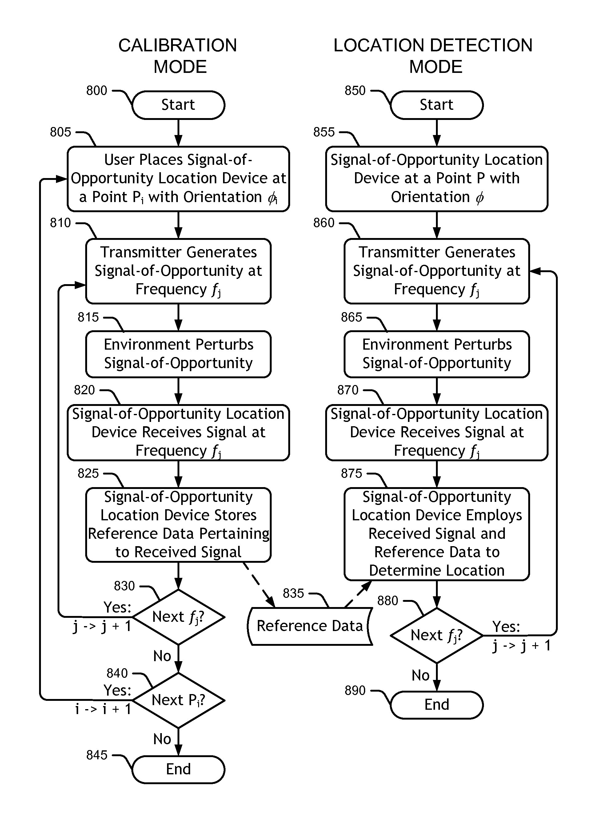
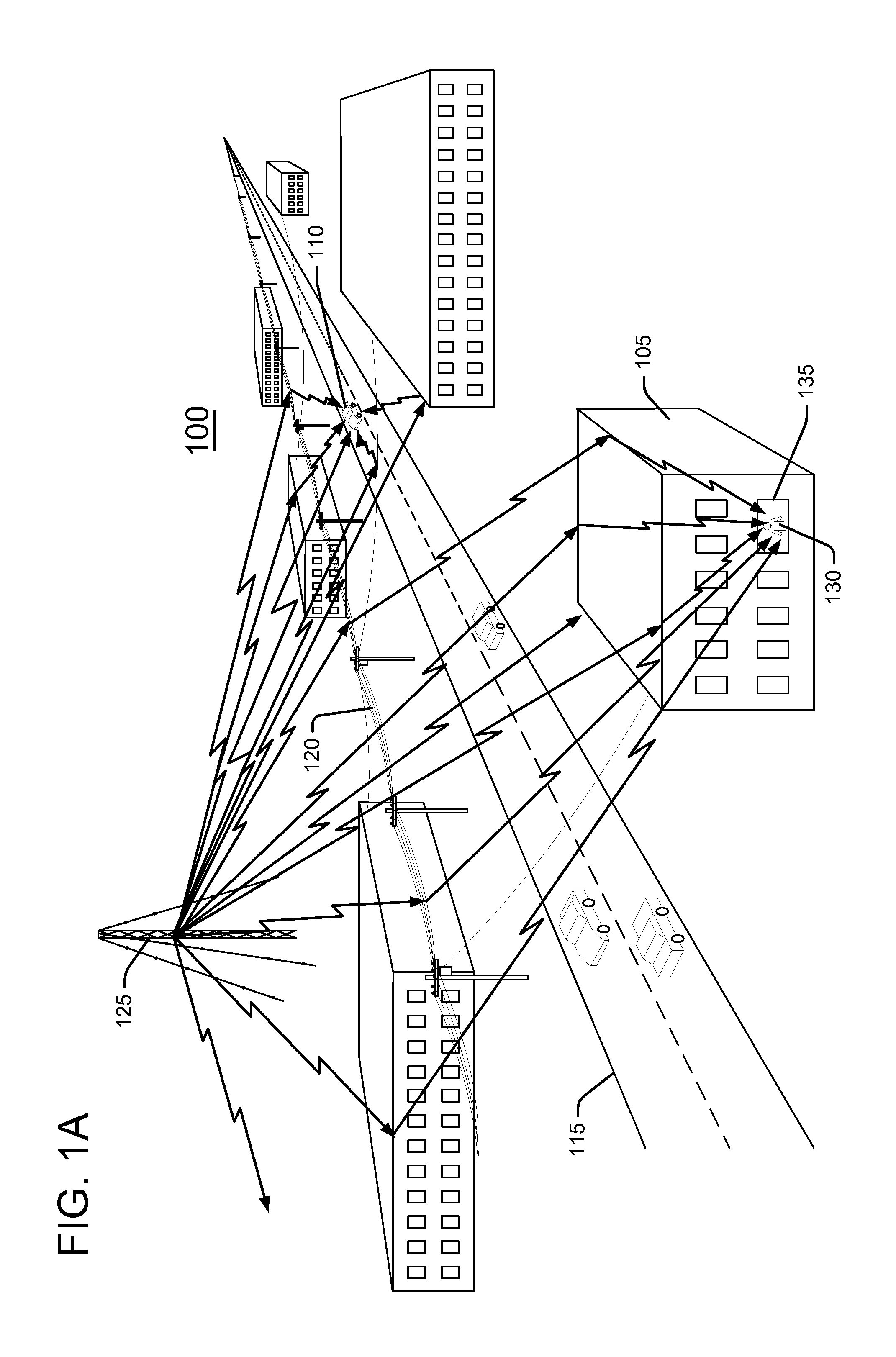
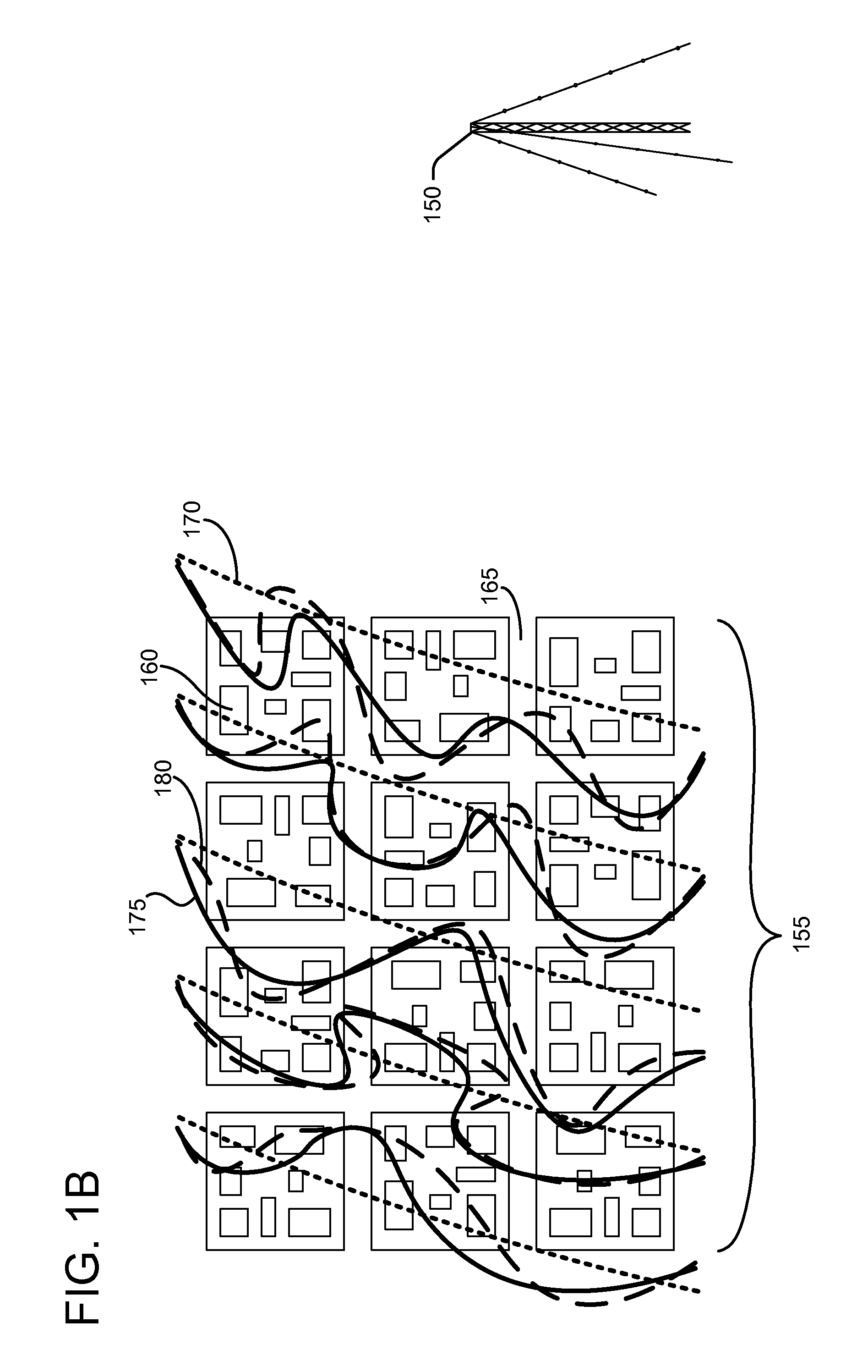
[0034]A preferred embodiment of the disclosed location determining system employs “signals-of-opportunity” in the standard broadcast AM band to determine the location of a particular radio receiver. Some conventional RF fingerprinting approaches may locate a mobile transmitter with respect to a network of local receivers using frequencies not associated with the standard broadcast AM band. However, in the preferred embodiment of the disclosed location determining system, a signal-of-opportunity location detector (SOLD), namely an individual receiver, locates itself with respect to a number of distant AM broadcast stations. Other embodiments may employ other frequencies less than or greater than those of the standard broadcast AM band (520 KHz-1710 KHz) depending on the particular application.

[0035]Near field electromagnetic ranging (NFER) is a technique useful for determining location. One NFER approach uses a local beacon transmitter and a locator receiver. The beacon transmitter t...


PUM


Abstract

A signal-of-opportunity location device (SOLD) that may be situated in a complex radio propagation environment with multiple RF signal obstructions receives RF signals from a distant transmitter. The RF signals from the distant transmitter interact with obstructions in the propagation environment local to the SOLD. The local obstructions perturb the RF signals causing the RF signals to exhibit near field behavior in the complex radio propagation environment. The SOLD receives the locally perturbed signals. The SOLD detects signal characteristics of RF signal components of the received signals and compares these signal characteristics with reference data in a reference data store to determine the current location of the SOLD.

Description

[0001]This invention was made with Government support under Contract FA8651-09-M-0175 awarded by the US Air Force. The government has certain rights in the invention.BACKGROUND[0002]The disclosures herein relate generally to location determining systems, and more specifically, to systems that determine location using radio signals.[0003]Numerous systems have been developed throughout the years to determine location using radio signals. Some of these techniques include triangulation, radio ranging from a collection of direction finding measurements, passive and active tag ranging, time difference of arrival (TDOA) systems and global positioning systems (GPS), for example. These techniques rely on measurements in the “far field” of a radio transmitter. In other words, these measurements are performed at a substantial distance away from the radio transmitter in terms of radio signal wavelength.[0004]The urban environment exerts a substantial impact on the propagation of radio frequency...

Claims


Application Information

Patent Timeline
IPC IPC(8): G01S3/02
CPCG01S5/0252G01S5/0221G01S5/02213G01S5/02521
Inventor SCHANTZ, HANS GREGORYUNDEN, ALFRED HANSRICHARDS, ERICDEPIERRE, ROBERT EDWARD
Owner GAN CORP
Why Eureka
Try Eureka