
Radio wave propagation environment measurement device, wireless network construction system and radio wave propagation environment measurement method

A technology for wireless network system and environmental measurement, which is applied in the field of radio wave propagation environment measurement devices, and can solve problems such as unknown electromagnetic wave transmission characteristics

Inactive Publication Date: 2014-02-26
HITACHI LTD
View PDF6 Cites 13 Cited by
  • Summary
  • Abstract
  • Description
  • Claims
  • Application Information

AI Technical Summary

Problems solved by technology

In addition, since only the surface shape is obtained as a polygonal model, the transmission characteristics of electromagnetic waves propagating through the shape are also unknown.

Method used


Image

  • Radio wave propagation environment measurement device, wireless network construction system and radio wave propagation environment measurement method
  • Radio wave propagation environment measurement device, wireless network construction system and radio wave propagation environment measurement method
  • Radio wave propagation environment measurement device, wireless network construction system and radio wave propagation environment measurement method

Examples


Embodiment 1

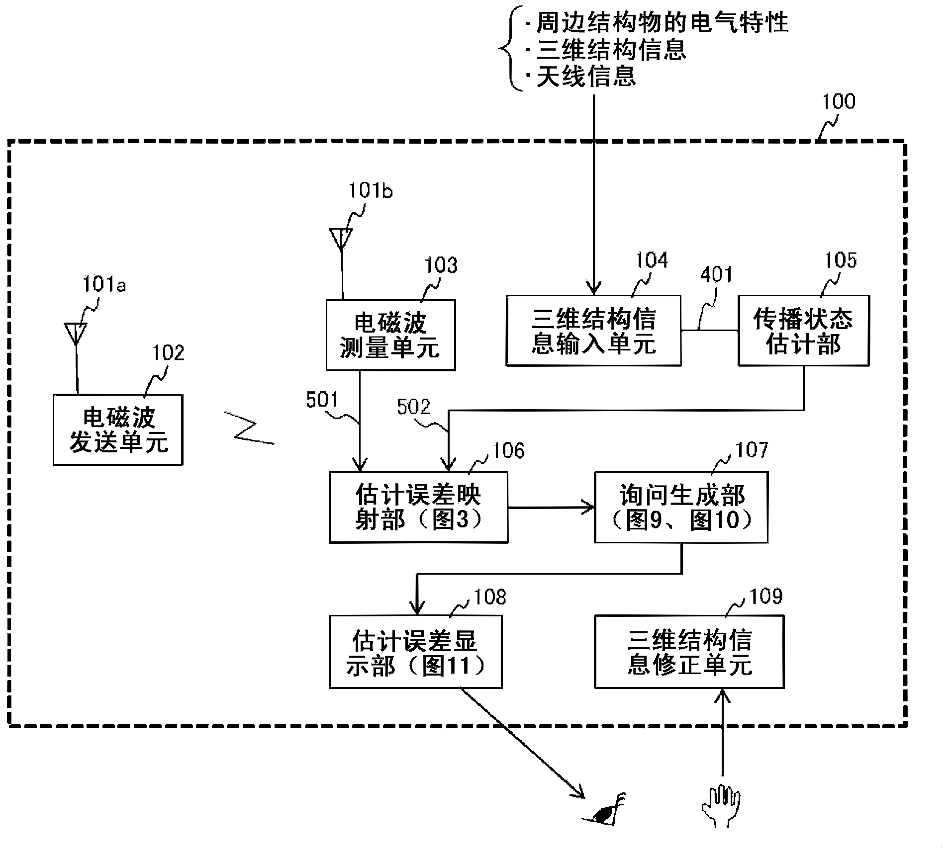
[0046] figure 1 It is a diagram showing a configuration example of the radio wave propagation environment measurement device 100 according to the first embodiment of the present invention. The radio wave propagation environment measurement device 100 includes an electromagnetic wave transmitting unit 102 including a transmitting antenna 101a, an electromagnetic wave measuring unit 103 including a receiving antenna 101b, a three-dimensional structure information input unit 104, a propagation state estimation unit 105, an estimation error mapping unit 106, and a query generation unit 107. , an estimation error display unit 108, and a three-dimensional structure information correction unit 109.

[0047] Describe in detail in the following order figure 1 The configuration of the radio wave propagation environment measurement device 100 will be explained first. Here, one input 501 to the estimation error mapping unit 106 is actually measured data (measured value) from the electro...

Embodiment 2

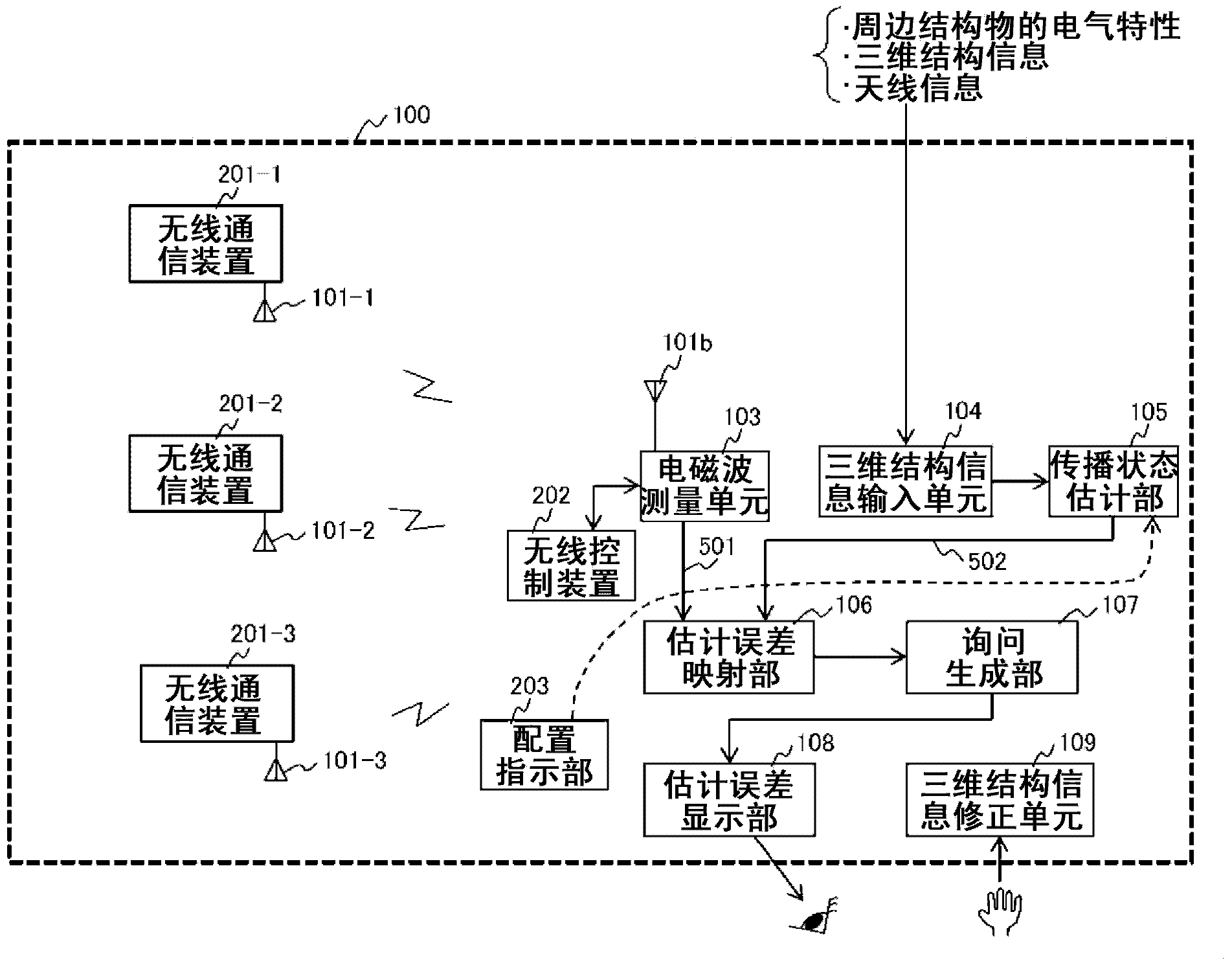
[0134] figure 2 The second embodiment of the present invention is shown. The main focus of embodiment 1 is to measure the radio wave propagation environment, and to correct information such as site structures. In the second embodiment, there is provided a wireless network construction system that can teach a more suitable installation position even in the case of an antenna installation position in a bad communication environment.

[0135] figure 2 The radio wave propagation environment measurement device 100 relative to figure 1 The shown radio wave propagation environment measurement device 100 is different in that the electromagnetic wave transmitting unit 102 is composed of a plurality of wireless communication devices 201 , has a wireless control device 202 , and has a placement instruction unit 203 .

[0136] in addition, Figure 13 As shown, wireless communication devices 201 - 1 to 201 - 3 are arranged at various places in a site where a wireless network system i...

Embodiment 3

[0142] The radio wave propagation environment measurement device according to the third embodiment of the present invention includes a material property database.

[0143] exist Figure 12 In the inquiries 1203 and 1204 for material change, the direction and error amount of each property change are displayed in a list from high to low relative to the material properties registered in the material property database, and the user can select from them.

[0144] That is, for each error amount caused by electrical material properties, and the direction of too small or too large, it is possible to obtain the reflection attenuation and transmission attenuation based on the electrical material properties before correction and each property value in the material property database. The difference between the amount and the diffraction attenuation amount is taken out as a list from the highest correlation.

[0145] As described above, according to the third embodiment of the present inv...


PUM


Abstract

The purpose of the present invention is to easily obtain three-dimensional shape data and material characteristics data that are necessary for estimating radio wave propagation between wireless stations, in order to construct a highly reliable wireless network. In the present invention, a wireless network system is provided with wireless signal transmission and reception equipment at a planned construction site. An electromagnetic wave measurement value for a wireless signal between the equipment is obtained. Three-dimensional structure information that includes the electrical characteristics and three-dimensional shape information of structures that comprise the site is used to estimate a propagation state of an electromagnetic wave for a wireless signal between the wireless signal transmission and reception equipment, and thereby an electromagnetic estimation value is obtained. An electromagnetic wave measurement value expressed as a signal intensity at each time point and an electromagnetic wave estimation value are compared for each time point to obtain a time zone in which such resultant error value is larger than a reference value. The path between the wireless signal transmission and reception equipment that is receiving in such time zone is calculated as the electromagnetic wave path. The three-dimensional structure information for the site positioned on the electromagnetic wave path is corrected and the electromagnetic wave estimation value is re-calculated. The electromagnetic wave measurement value and the re-calculated electromagnetic wave estimation value are compared to obtain corrected information for three-dimensional structure information with a smaller error value.

Description

technical field [0001] The present invention relates to a radio wave propagation environment measurement device, a wireless network construction system, and a radio wave propagation environment measurement method for supporting radio wave propagation environment design in a wireless network system. Background technique [0002] In the multi-hop wireless network communication technology, when communication is performed between desired wireless stations, a plurality of wireless stations are installed between the wireless stations as relay stations, and data is transmitted and received in a multi-hop manner. [0003] Especially in recent years, with the cost reduction of wireless communication equipment such as wireless LAN (Local Area Network, local area network), Bluetooth, a short-range wireless communication standard mainly for digital devices, and ZigBee, a short-range wireless communication standard mainly for home appliances, etc. The standardization of sensor network te...

Claims


Application Information

Patent Timeline
Patent Type & Authority Applications(China)
IPC IPC(8): H04B17/00
CPCH04B17/0065H04B17/0072H04W16/20H04B17/009H04W16/18H04B17/0057H04B17/20H04B17/23H04B17/27H04B17/318H04B17/391
Inventor 佐藤义人山田勉远藤浩通
Owner HITACHI LTD
Learn More