Method for Changing Frequency and Base Station in Radio Optical Fusion Communication System

a radio optical fusion and communication system technology, applied in the field of radio optical fusion communication system technology, can solve the problem of no proposed method for switching a radio frequency channel

Inactive Publication Date: 2007-09-06
SUMITOMO OSAKA CEMENT CO LTD
View PDF3 Cites 14 Cited by
  • Summary
  • Abstract
  • Description
  • Claims
  • Application Information

AI Technical Summary

Benefits of technology

[0025] According to the present invention, a base station utilizing the method for changing a frequency in the above-described radio optical fusion communication system can be provided.

Problems solved by technology

However, there is no proposed method for switching a radio frequency channel.

Method used


Image

  • Method for Changing Frequency and Base Station in Radio Optical Fusion Communication System
  • Method for Changing Frequency and Base Station in Radio Optical Fusion Communication System
  • Method for Changing Frequency and Base Station in Radio Optical Fusion Communication System

Examples


Embodiment Construction

[0036] An embodiment disclosed as the best mode for carrying out the present invention will now be described with reference to the drawings. The embodiment is not limited to the following example.

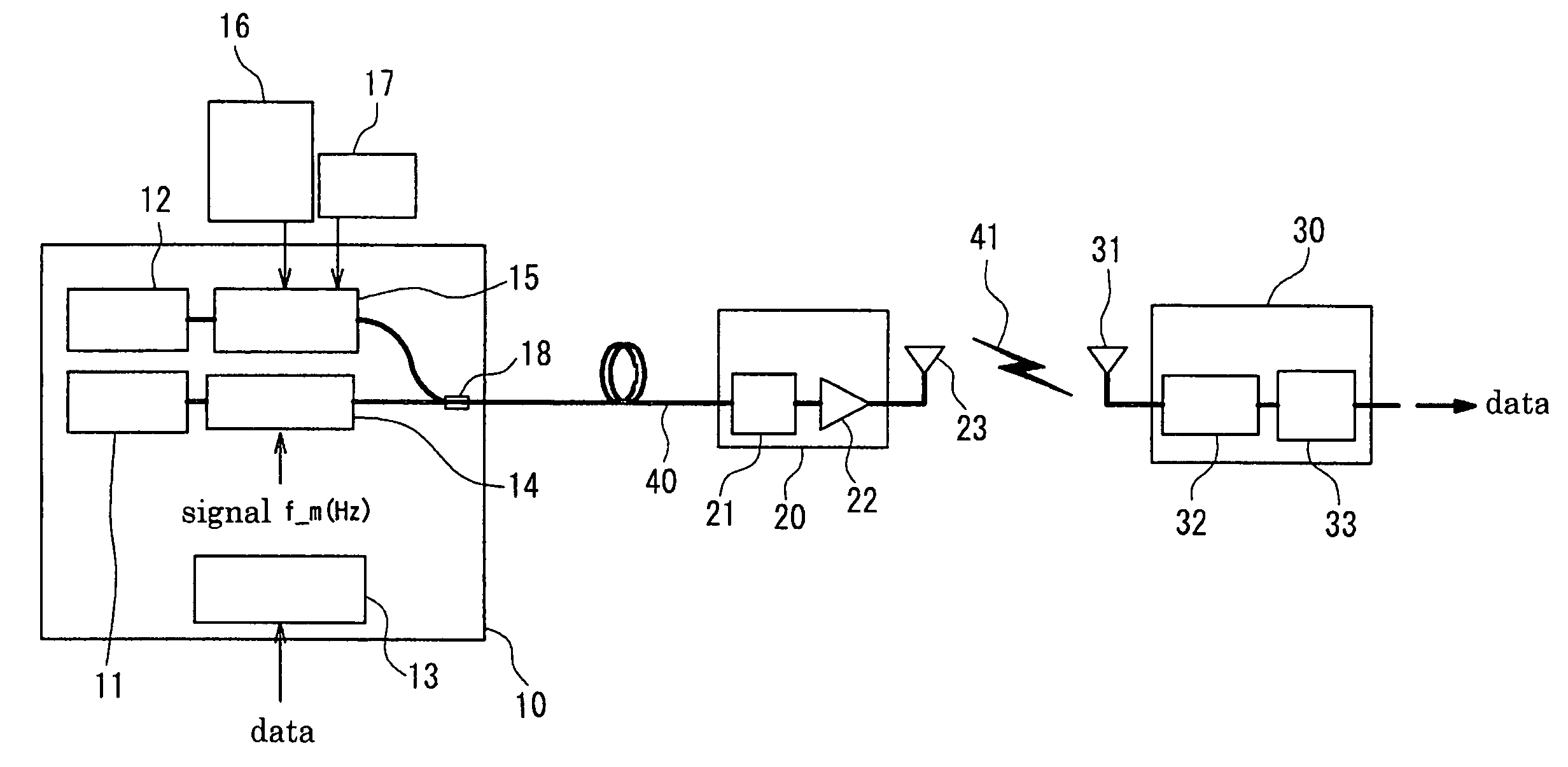
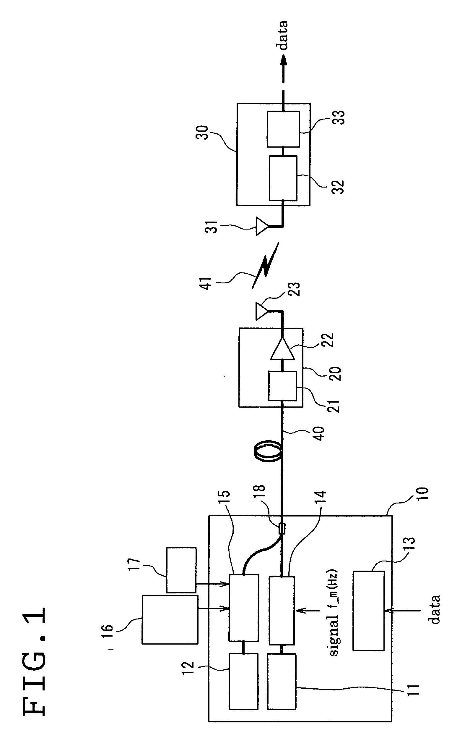
[0037]FIG. 1 shows the entire structure of a radio optical fusion communication system according to the present invention. Fundamental elements of the system are the same as those in the structure shown in FIG. 10. In other words, the system includes a base station (10), a remote antenna station (20), and a receiving terminal (30). The base station (10) is connected to the remote antenna station (20) via an optical fiber transmission path (40). The remote antenna station (20) is connected to the receiving terminal (30) via a radio propagation path (41).

[0038] As described above, the base station (10) includes a first laser light source (11) for single-mode oscillation at an oscillation frequency f1 (Hz), a second laser light source (12) for oscillation at an oscillation frequency f2 (Hz),...


PUM

PropertyMeasurementUnit
frequencyaaaaaaaaaa
intermediate-frequencyaaaaaaaaaa
optical transmissionaaaaaaaaaa

Abstract

In a radio optical fusion communication system with the integration of an optical fiber transmission path and a radio propagation path, wherein by first and second light sources, an intermediate-frequency signal generating means for generating a modulating signal at an intermediate frequency band, a modulator for modulating an optical signal from the first light source into an SSB modulated optical signal using the intermediate-frequency signal, and an optical mixer for mixing the modulated optical signal with the optical signal from the second light source to obtain an optical transmission signal in a base station, the frequency of either of the optical signals is controlled such that the difference in frequency between the optical signals is a desired frequency of a modulated radio signal, thus switching the frequency channel of the modulated radio signal in the radio propagation path.

Description

TECHNICAL FIELD [0001] The present invention relates to a radio optical fusion communication system with the integration of optical fiber transmission and radio communication, and in particular, relates to a technique for changing a radio frequency in the radio optical fusion communication system. BACKGROUND ART [0002] The present inventors have researched and proposed a radio optical fusion communication system with an integration of optical fiber transmission and a radio communication. Particularly, in a method proposed by the present inventors, optical signals are generated using a first laser light source and a second laser light source of different wavelengths, the first optical signal is modulated into an unsuppressed-carrier single-sideband (SSB) or double-sideband (DSB) modulated optical signal using an intermediate-frequency signal, the modulated signal is mixed with the second optical signal, and the resultant optical signal is transmitted. [0003] The optical signal is opt...

Claims


Application Information

Patent Timeline
Patent Type & Authority Applications(United States)
IPC IPC(8): H04B10/04H04B10/06H04Q7/20G02F2/02G02F1/225G02F2/00H04B10/516H04B10/54H04B10/61H04W16/02H04W88/08H04W92/00
CPCG02F1/2255H04B10/25758G02F2/002G02F2/00H04B10/25H04B10/2575H04W16/00
Inventor SHOJI, YOZOOGAWA, HIROYOHASHIMOTO, YOSHIHIRO
Owner SUMITOMO OSAKA CEMENT CO LTD
Why Eureka
Try Eureka