Moulding tool for moulding a ceramic green body and use of said moulding tool

Inactive Publication Date: 2011-09-13
SCHOTT AG
View PDF8 Cites 2 Cited by
  • Summary
  • Abstract
  • Description
  • Claims
  • Application Information

AI Technical Summary

Benefits of technology

[0042]It is hence desirable to significantly simplify the process and to reduce and possibly even avoid grinding, i.e. reduce post-processing while fulfilling highest

Problems solved by technology

This will

Method used


Image

  • Moulding tool for moulding a ceramic green body and use of said moulding tool
  • Moulding tool for moulding a ceramic green body and use of said moulding tool
  • Moulding tool for moulding a ceramic green body and use of said moulding tool

Examples


Example

EXEMPLARY EMBODIMENT 1 FOR A LENS 110

See FIG. 3

[0105]FIG. 3 shows a lens 110 produced by use of the moulding tool according to the present invention for the application of digital projection with the following parameters:

[0106]left surface 111right surface 112diameter D15 mmthickness d 4 mmcurveconvexconcaveradius of the curve17.77 mm36.24 mmK−0.458 (asphere)0 (sphere)a12.92E−30a23.87E−30a34.40E−80a400applicationdigital projection

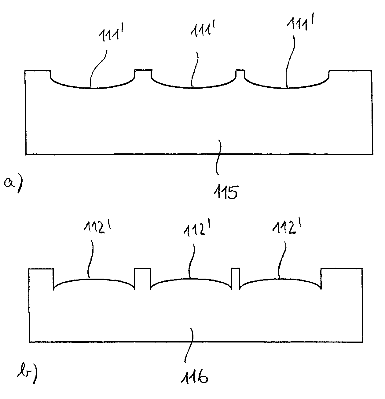
[0107]A moulding tool according to the present invention 115 for slip casting is shown in FIG. 4a, displaying the convex left surface 111 with the contour 111′. A moulding tool according to the present invention 116 for slip casting is shown in FIG. 4b, displaying the concave right surface 112 with the contour 112′. In any of the shown moulding tools 115 and 116 there are contours 111′ and 112′ for three lenses, being laterally located next to each other. The moulding tool does not have to be limited to the contours of three lenses but could also comprise o...

Example

EMBODIMENT 2 FOR A LENS 210

See FIG. 7

[0113]FIG. 7 shows a lens 210 obtained by using a moulding tool according to the present invention for application in the field of digital photography (DSC camera) with the following parameters:

[0114]left surface 211right surface 212diameterD1 = 9.89 mmD2 = 8.47 mmthickness d 2.86 mmcurveconvexconvexradius of the curve26.332 mmK0 (sphere)0 (sphere)applicationDSC camera

[0115]FIG. 8 shows moulding tool pairs 215, 216 resting above each other for slip casting, wherein the entire tool composed from moulding tool parts 215, 216 displays both surfaces 211, 212 of lens 210. The pairs of contours 211′ and 212′ each show the shape of a lens. In order to obtain a body that is as massive and as homogeneous as possible, the volume shrinkage by sherd formation can be balanced by re-filling slip into the mould. The re-filling of slip takes place through a channel 218 that is present within the moulding tool 215 leading to each of the lens contours.

Example

EMBODIMENT 3 FOR A LENS 310

See FIG. 9

[0116]FIG. 9 shows a lens 310 obtained by using a moulding tool according to the present invention for application in the field of digital photography (SLR camera) with the following parameters:

[0117]left surface 311right surface 312diameterD1 = 8.55 mmD2 = 11.82 mmthickness d3.4 mmcurveconcaveconvexradius of the curve13.68 mm12.46 mmk5.22 (asphere)0 (sphere)a100a2−9.523E−50a300a45.653E−90applicationdigital photography (SLR)


PUM

PropertyMeasurementUnit
Lengthaaaaaaaaaa
Surface roughnessaaaaaaaaaa

Abstract

The moulding tool is a near-net-shape negative mould for shaping a ceramic green body for the lens. The mould has a shaping surface, which is described by the following equation B:
y1=cz21+1-(k+1)c2z2+a1z2+a2z4+a3z6+a4z8+,(B)
y1 gives a position on an optical axis; x designates a perpendicular distance from the optical axis to the surface; k, c, and a1, a2, a3, a4, . . . are constants describing a surface of the lens to be moulded and z=|x|+b, wherein b is a constant with a value greater than 0 and less than 0.3 mm, which is a measure of a deviation of the shaping surface from the surface of the lens.

Description

BACKGROUND OF THE INVENTION[0001]The present invention relates to a moulding tool for moulding a ceramic green body in the production of at least one optical lens made of an opto-ceramic. The invention furthermore addresses a process for producing the lenses mentioned before. Also, the invention is directed to the use of a moulding tool for producing opto-ceramic lenses.[0002]Transparent ceramics suited as materials for lenses are hereinafter referred to as opto-ceramics. Such materials have very convenient properties (refractive indices, dispersions) and contribute to an improvement of optical imaging systems. In special cases new imaging concepts are only possible with such new optical material options. Especially the possibilities of more compact construction of for example digital cameras or improved of simplified colour corrections (chromatical or apochromatical) or mentioned here.[0003]The lenses that can be produced with the moulding tool according to the invention and by mak...

Claims


Application Information

Patent Timeline
IPC IPC(8): G06F19/00G06F7/60
CPCB28B1/261B28B3/02C04B35/6455C04B2235/602C04B2235/6027G02B1/00Y10S425/808
Inventor MENKE, YVONNEPEUCHERT, ULRICHOKANO, YOSHIOREICHEL, STEFFEN
Owner SCHOTT AG
Why Eureka
Try Eureka