
Floor sweeper with cloth cleaning pad

a floor sweeper and cloth cleaning technology, which is applied in the field of hand-held floor sweepers, can solve the problems of not having a cloth portion and not solving the problem of catching and retaining small dust particles, and achieve the effect of convenient removal for washing and replacemen

Inactive Publication Date: 2011-09-20
KALETA BRYAN +1
View PDF8 Cites 51 Cited by
  • Summary
  • Abstract
  • Description
  • Claims
  • Application Information

AI Technical Summary

Benefits of technology

The sweeper effectively picks up both large and small particles, easily maneuvering under furniture and low-lying objects, with the cleaning pad ensuring thorough dust removal and easy maintenance.

Problems solved by technology

A problem with this type of floor sweeper is that it only picks up material in the forward or rearward direction as the user pushes or pulls the sweeper across the floor as the sweeper is designed for movement in just the forward or reward directions.
Another problem not solved by this type of sweeper is that it does not have a cloth portion that removes very small dust particles from the floor.
However, it does not solve the problem of catching and retaining small dust particles on a hard surface that were not swept into the dust tray by the brushes.

Method used


Image

  • Floor sweeper with cloth cleaning pad
  • Floor sweeper with cloth cleaning pad
  • Floor sweeper with cloth cleaning pad

Examples


Embodiment Construction

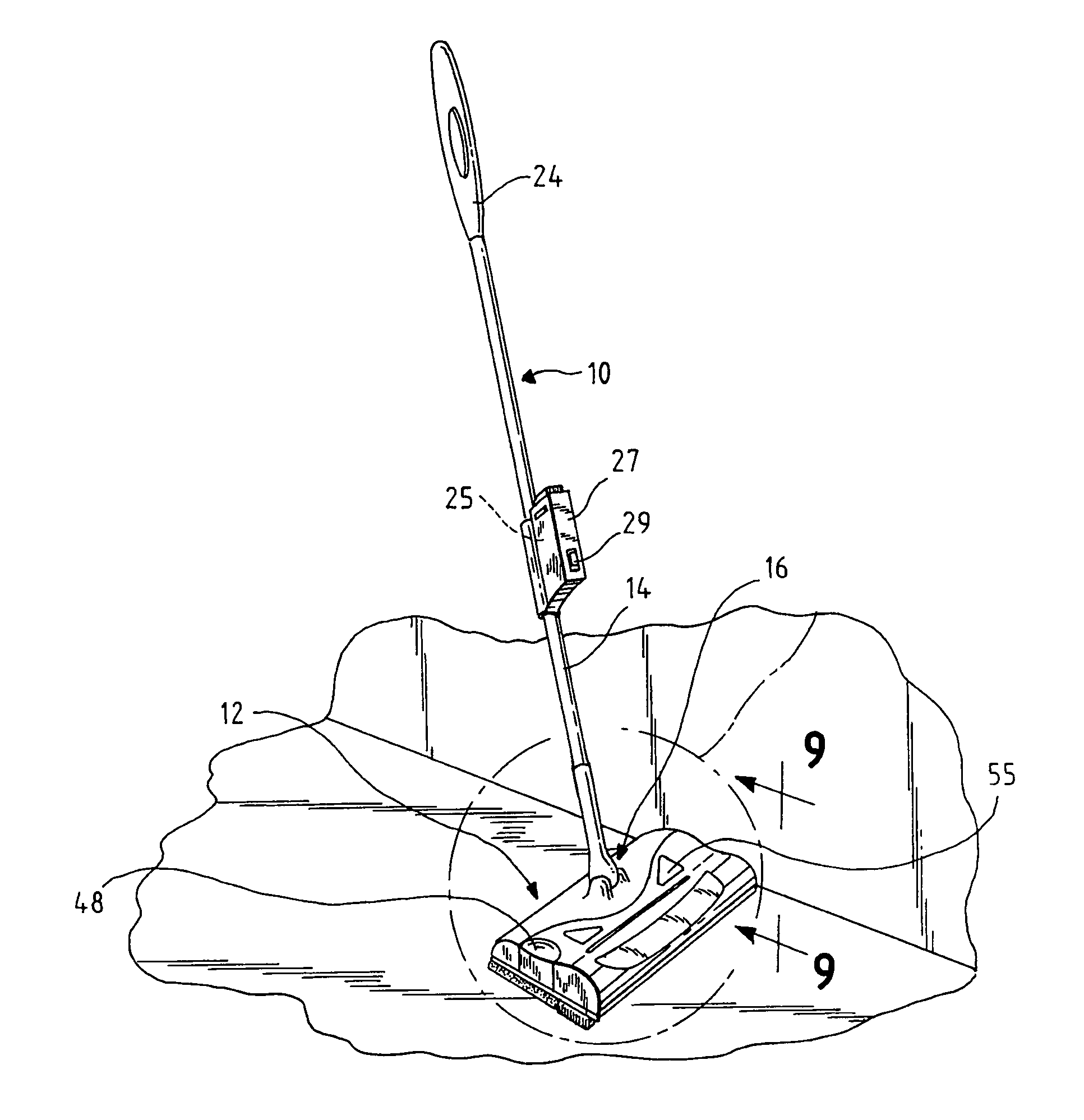
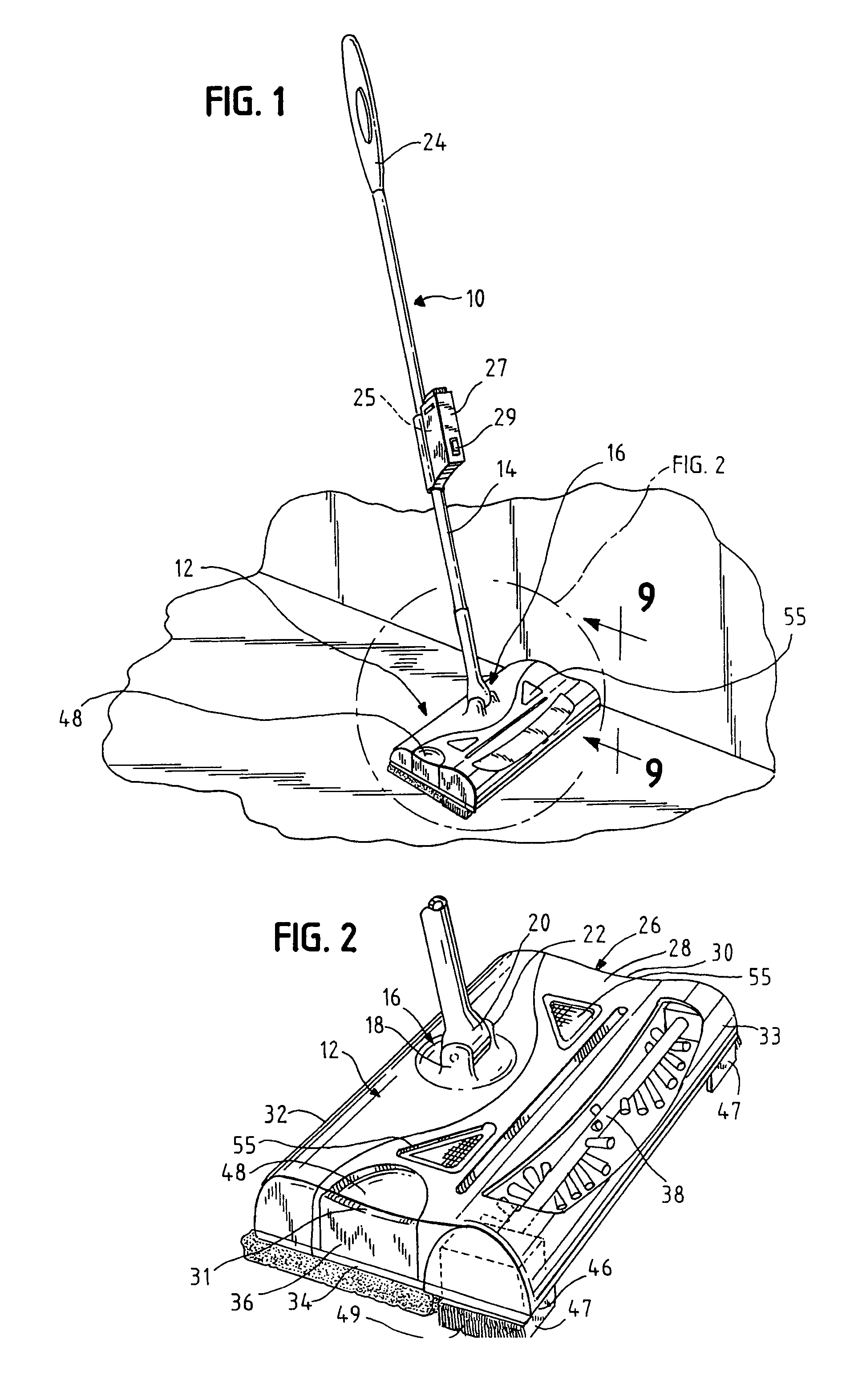
[0019]Turning first to FIGS. 1 and 2 a sweeper 10 of the present invention is disclosed. There is a sweeper head 12 connected to an elongated handle 14 by means of a universal pivot 16. The handle 14 is assembled from a series of interlocking pipes or tubes. Spring loaded pins or locks are placed in one end of each of the tubes which interlock with receiving holes in the next adjacent tube. One end of each of tubes has a reduced diameter to be received in the end of the next tube above it so that the receiving tube slides over the reduced diameter end of the inserted tube.

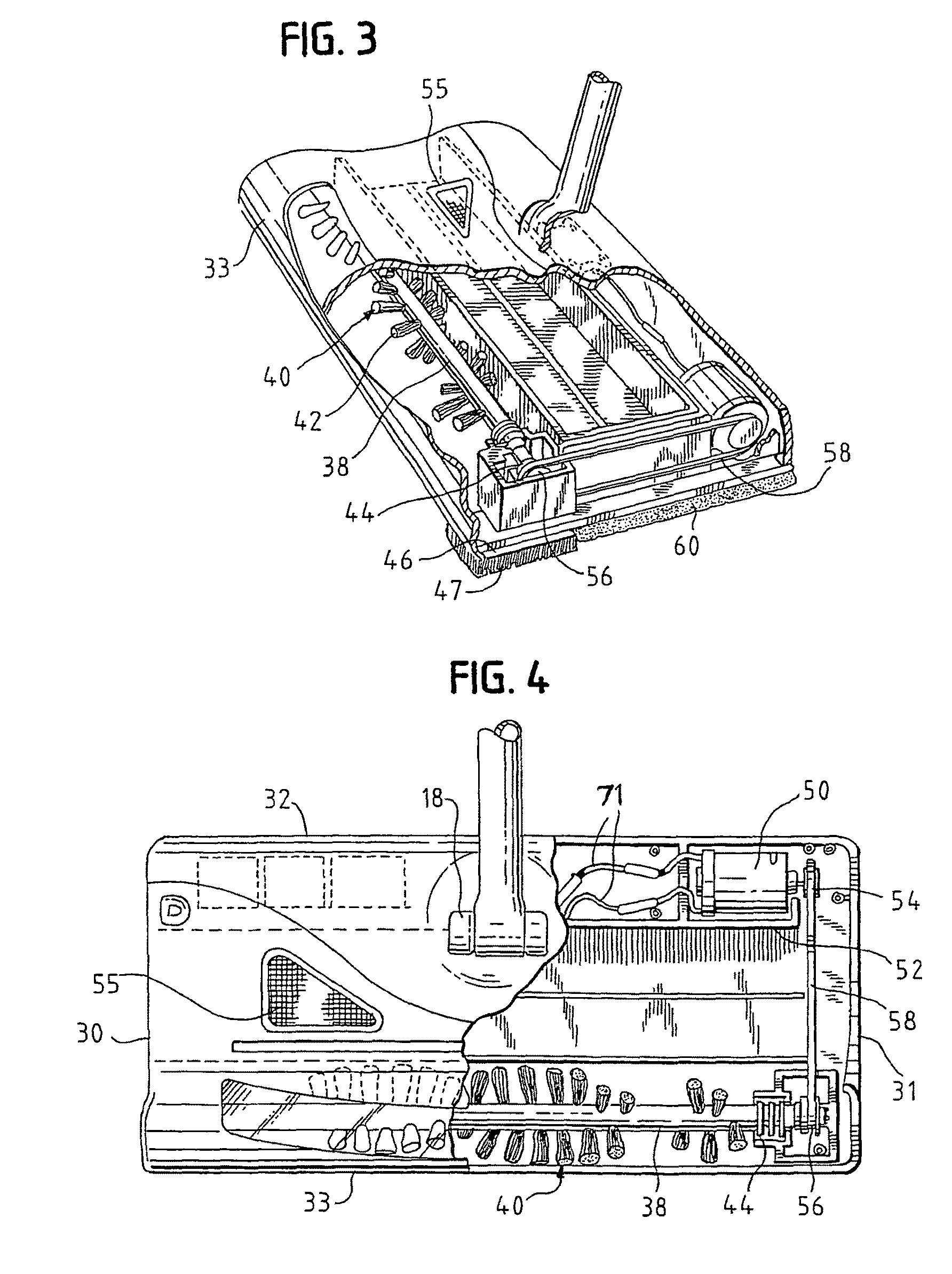
[0020]The universal pivot 16 is comprised of a pair of universal pivot supports 18 attached to the head 12. A rotatable ball 20 is mounted on a shaft supported by the universal pivot supports 18. A yoke 22 at the bottom of the handle 14 is rotatably mounted to the ball 20 in a conventional manner to form the universal pivot connection 16. Other types of universal pivot connections can be utilized as will be apparen...


PUM


Abstract

A light weight floor sweeper having a very low profile sweeper head that uses a sweeping brush and cleaning pad to slide across the surface to be cleaned. The floor sweeper head is mounted to an elongated handle by means of a universal pivot or universal joint which allows the floor sweeper head to easily pivot about the handle in any direction to pick up debris under over hanging cabinets or under furniture. A sweeping brush is mounted on the bottom of the sweeper head to provide sweeping action as the floor sweeper is moved in any direction. Furthermore there is a soft cleaning pad releasably mounted adjacent to the brush to entrap dust and particles that the brush does not pick up. The brush is powered by a small electric motor. A removable dust-receiving tray is mounted in the sweeper head to receive debris swept by the brush.

Description

FIELD OF THE INVENTION[0001]This invention relates to handheld floor sweepers and more particularly to a hand held floor sweeper having a sweeping brush powered by an electric motor and a soft cleaning pad for picking up dirt and dust. The inventive sweeper is particularly well suited for cleaning hard floor surfaces such as wood, ceramic tile and marble.[0002]Handheld sweepers have been used in the past to pick up dust and small items from hard surfaces such as wood or tile floors. One type of handheld floor sweeper that has been used extensively in the past is a manually pushed floor sweeper that is not powered by a motor. The handheld sweeper has brushes mounted on a shaft located in the sweeper head that contact the surface to be cleaned. The brushes rotate as the sweeper is pushed and pulled across the floor surface. As the brushes rotate they sweep the loose material up into a dust canister or similar dust-receiving portion in the sweeper head. A problem with this type of floo...

Claims


Application Information

Patent Timeline
Patent Type & Authority Patents(United States)
IPC IPC(8): A47L13/00A47L11/24A47L11/32
CPCA47L11/33A47L11/4013A47L11/4025A47L11/4036A47L11/4041A47L11/4069A47L11/4075A47L13/12A47L13/16
Inventor KALETA, BRYANKALETA, MARK
Owner KALETA BRYAN
Learn More