Transmitting torque limiting apparatus for vehicle

a technology of transmission apparatus and torque limit, which is applied in the direction of slip coupling, coupling, gearing, etc., can solve the problems of reducing shortening the transmission capacity of the rotary shaft, and affecting the quality of the vehicle, so as to limit the inputting of excessive torque

Inactive Publication Date: 2011-09-20
TOYOTA JIDOSHA KK
View PDF14 Cites 10 Cited by
  • Summary
  • Abstract
  • Description
  • Claims
  • Application Information

AI Technical Summary

Benefits of technology

[0006]The present invention was made in view of the circumstances described above. It is therefore an object of the present invention to provide a transmitting torque limiting apparatus which is used in the power transmitting apparatus and which can limit inputting of the excessive torque thereinto resulted from the quick start of vehicle and the like, without inviting large-size or heavy-weight of the power transmission apparatus.
[0016]According to the invention recited in the claims 5 and 6, the pressurized hydraulic circuit can apply the biasing force larger than that of the disc spring or the coil spring, which is effective when the present invention is applied to the special vehicle which requires larger limiting force.
[0021]The invention recited in the claim 9 is featured by the transmitting torque limiting apparatus, wherein each of the side gears has an annular shape, each of the side gear pieces has an annular shape having a diameter smaller than that of the side gear, and the side gear piece is held in a recess formed on an end surface of the side gear in a nested state. According to the invention recited in the claim 9 in which the gear piece is held in the side gear in the nested state, total axial length of the side gear and the side gear piece can be shortened.

Problems solved by technology

This may cause a temporary shortage of the transmission capacity of a rotary shaft such as a driving shaft, propeller shaft and the like, or capacity of gears arranged in a differential device, automatic transmission device and the like.
However, there is fear that strengthened shafts and the gears may make the power transmission apparatus large-sized and heavy-weighed, so that quality of the vehicle may be lowered.

Method used


Image

  • Transmitting torque limiting apparatus for vehicle
  • Transmitting torque limiting apparatus for vehicle
  • Transmitting torque limiting apparatus for vehicle

Examples


first embodiment

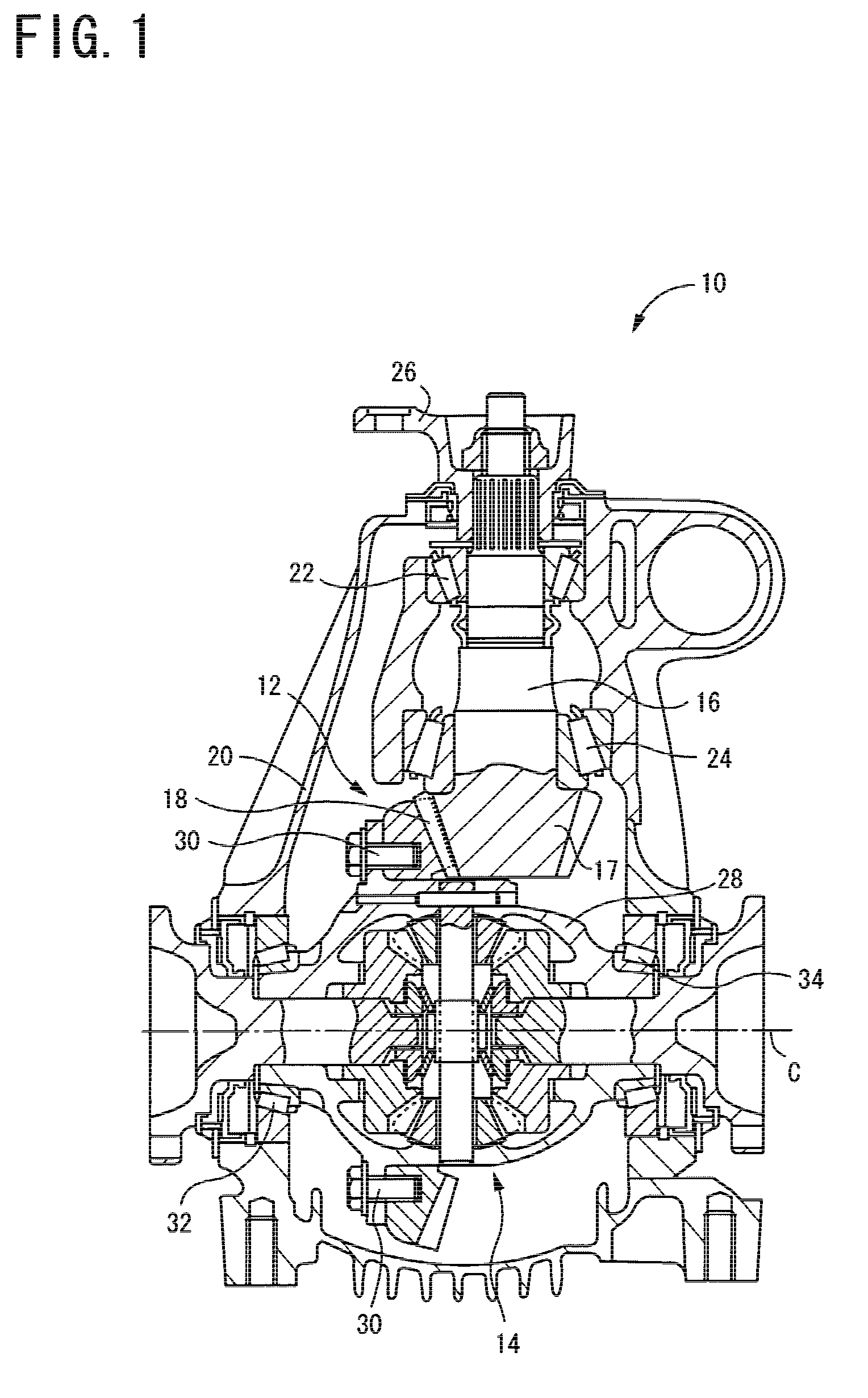
[0035]FIG. 1 is a cross section of a differential apparatus 10 which constructs a part of the power transmitting apparatus and which shows one embodiment of the present invention. This differential apparatus 10 is used in a FR (front engine, rear drive) type vehicle at a rear part thereof, to absorb difference of the number of rotations between the left wheel and the right wheel for allowing the vehicle to run along a curved road. Driving torque generated at an engine (not shown) is, after gear-shifted at a transmission (not shown), transmitted to the differential apparatus 10 via a propeller shaft (not shown).

[0036]The differential apparatus 10 includes a final reduction device 12 and a differential gear unit 14 constructed integral with each other. The final reduction device 12 is constructed by a drive pinion 16, and a ring gear 18 meshed therewith. The drive pinion 16 is joined to a rear end of the propeller shaft and is rotatably supported by a fixed housing 20 via bearings 22 ...

second embodiment

[0062]Next, a second embodiment of the present invention will be explained. In the following explanation, members having structure which is the same as the first embodiment are shown by the same reference numerals and detail explanation thereof is omitted.

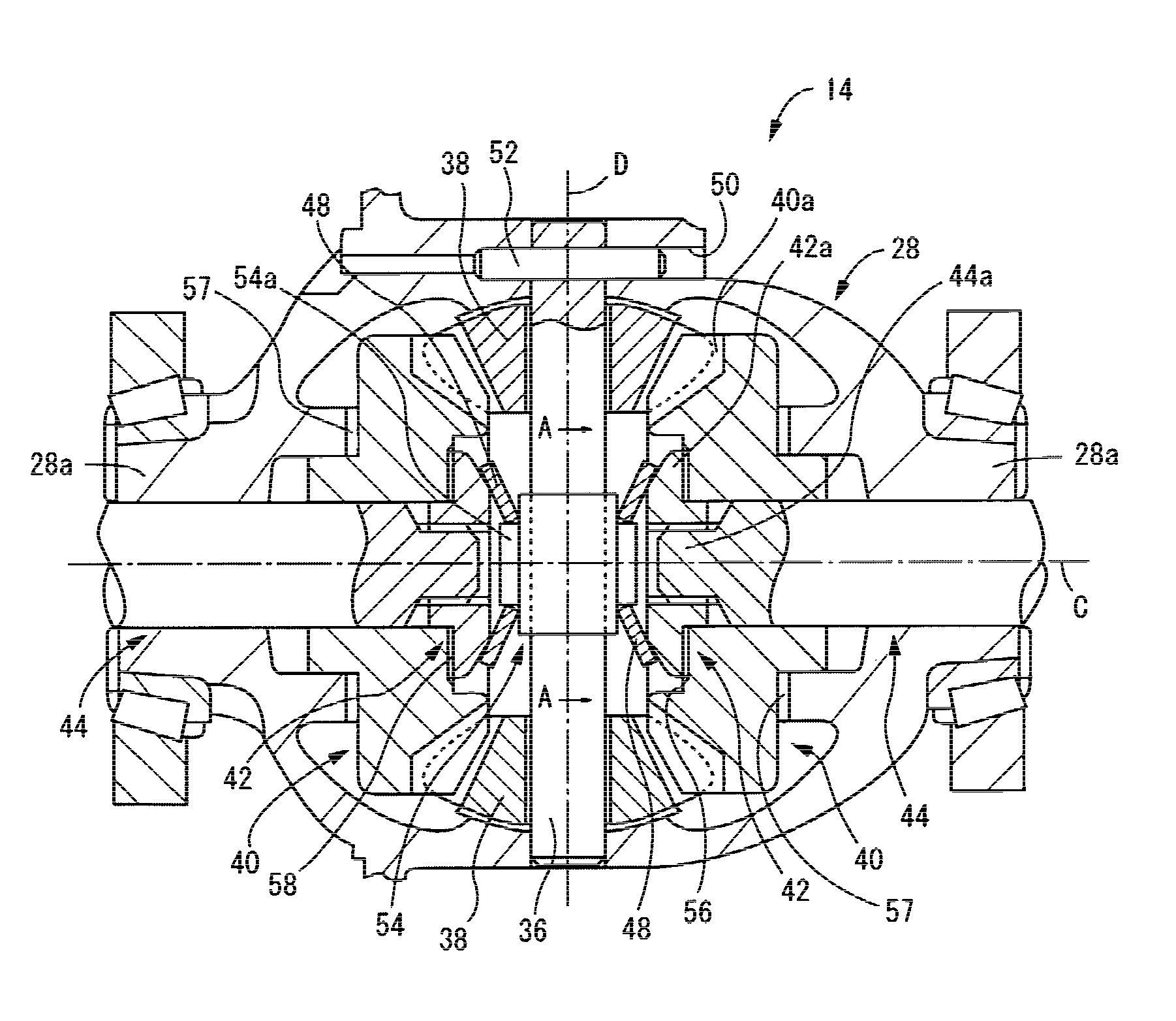
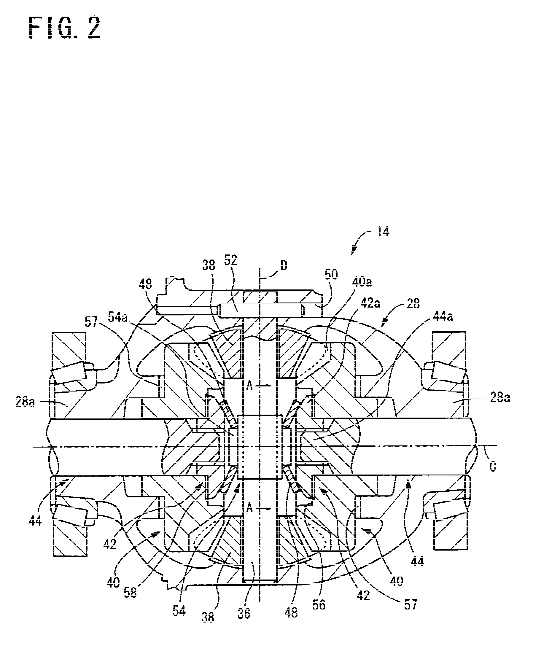
[0063]FIG. 5 is a partial cross section showing a differential gear unit 80 according to the second embodiment. The differential gear unit 80 has modified structure of a paired side gears 82, the paired side gear pieces 84, and paired side gear shafts 86, and the biasing mechanism is comprised of a coil spring 88, compared with the differential gear unit 14 in the first embodiment.

[0064]In detail, on an inner peripheral surface of a hole of each hollow side gear 82, the cylindrical side gear piece 84 is spline-fitted, so that the side gear piece 84 is rotated integral with the side gear 82 but is axially slidable relative to the side gear 82. At one end of each side gear piece 84 facing to the pinion shaft 36, a cylindrical positio...

third embodiment

[0076]Next, a third embodiment of the present invention will be explained with reference to FIG. 8. In this explanation, the members having the same structure as the first embodiment are given the corresponding reference numerals for simplicity of the explanation.

[0077]FIG. 8 is a cross section of a main portion of a differential gear unit 100 according to the third embodiment. The differential gear unit 100 is different from the differential gear unit 80 of the second embodiment in the structure of a paired side gear pieces 102, a pinion shaft 104, and a differential case 106, and the biasing mechanism is comprised of a hydraulic circuit 115.

[0078]To the pinion shaft 104 a pair of hydraulic oil supplying shaft 108 of cylindrical shape are fixedly attached. One end of each hydraulic oil supplying shaft 108 is inserted into an oil hole 110 formed in an end of the side gear piece 102, so that the hydraulic oil supplying shaft 108 can be rotated relative to the side gear piece 102, and...


PUM


Abstract

A transmitting torque limiting apparatus, used in a power transmitting apparatus, includes side gears (40) and side gears piece (42) one of which are axially shiftable. The side gears (40) and the side gear pieces (42) respectively have first engaging teeth (60a) and second engaging teeth (60b) each being provided with a pressure angle (Alpha). Due to such pressure angle, when an excessive torque is inputted into the power transmitting apparatus, a thrust force (F1) is generated for disengaging the engagement between the first engaging teeth (60a) and second engaging teeth (60b). Thus, inputting of the excessive torque into the power transmitting apparatus can be limited.

Description

TECHNICAL FIELD[0001]The present invention relates to a transmitting torque limiting apparatus for vehicle, used for example in a power transmission apparatus, and limits an inputting of excessive torque into the power transmitting apparatus, upon for example a quick start of a vehicle.BACKGROUND ART[0002]The power transmission apparatus for vehicle is provided in a power transmitting path from an engine to driving wheels to transmit power generated at the engine to each of drive wheels. Normally, it is constructed by a transmission, propeller shaft, final reduction device, drive shaft and the like. For example, “New-type Car Manual TOYOTA CELSIOR” (issued by TOYOTA JIDOSHA KABUSHIKI KAISHA in November, 1988) disclosed a general final reduction apparatus which includes a reduction device and a differential device constructed integrally. A driving torque of the engine is inputted into the power transmitting device and then is transmitted to the driving wheels, while a reacting torque...

Claims


Application Information

Patent Timeline
Patent Type & Authority Patents(United States)
IPC IPC(8): F16H48/06F16H48/20F16D7/04F16D43/20F16H35/10F16H48/08F16H48/38F16H57/037F16H57/04
CPCF16H48/08F16H48/24F16H48/32F16H2048/085F16H2048/423F16H2200/2071
Inventor HOMAN, AKINORI
Owner TOYOTA JIDOSHA KK
Why Eureka
Try Eureka