Passive walking legged robot

a legged robot and passive technology, applied in the direction of programme control, distance measurement, electric programme control, etc., can solve the problems of unnatural gait, difficult in principle to realize a highly energy-efficient gait, and inability to achieve steady gait, etc., to achieve stable continuous walking, high energy-efficient gait, and stable global stabilization of fixed points

a legged robot and passive technology, applied in the direction of programme control, distance measurement, electric programme control, etc., can solve the problems of unnatural gait, difficult in principle to realize a highly energy-efficient gait, and inability to achieve steady gait, etc., to achieve stable continuous walking, high energy-efficient gait, and stable global stabilization of fixed points

US8024070B2Inactive Publication Date: 2011-09-20NAGOYA INSTITUTE OF TECHNOLOGY

Image

  • Passive walking legged robot
  • Passive walking legged robot
  • Passive walking legged robot

Examples


embodiment

First Embodiment

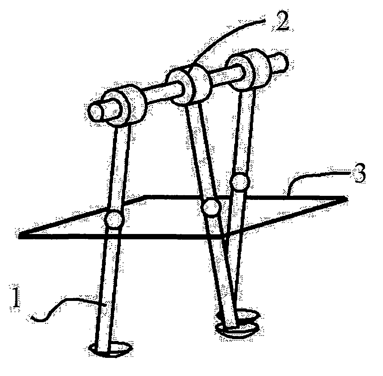
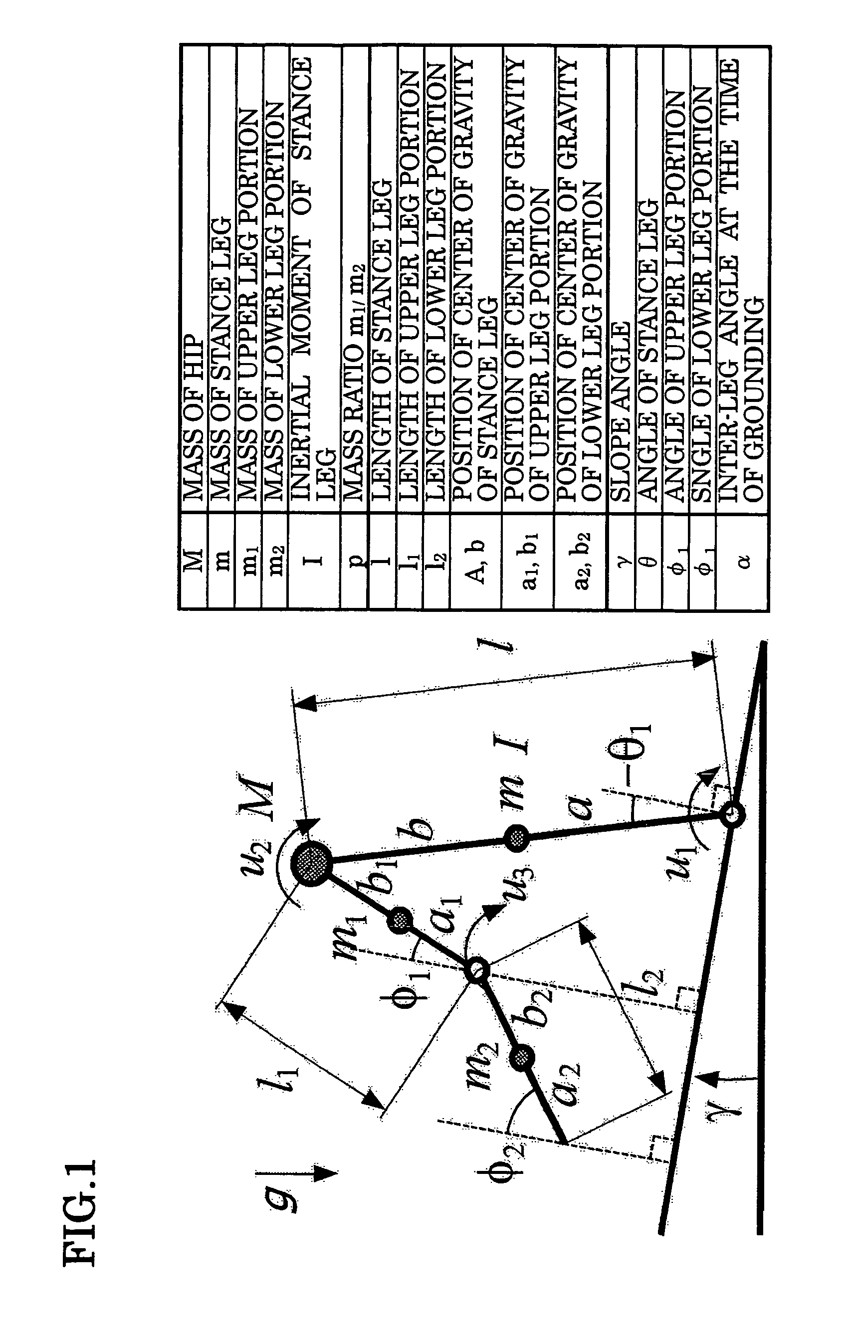
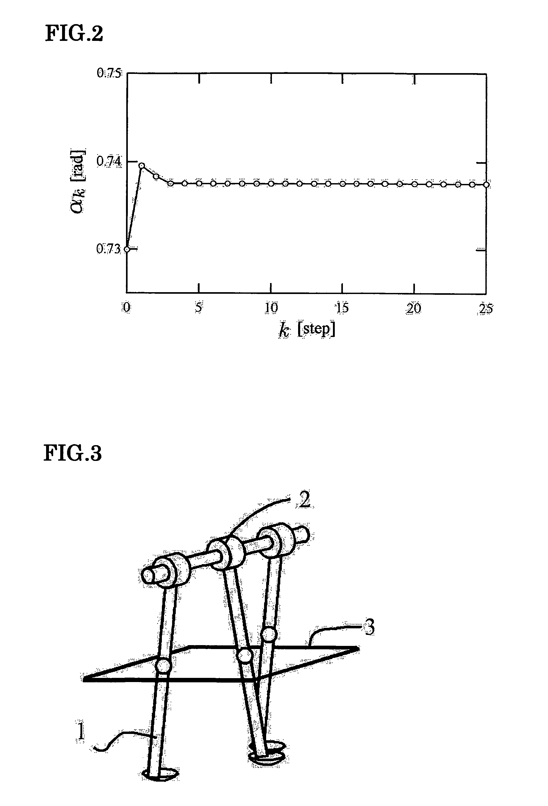
[0026]FIG. 1 schematically shows a legged mobile body having a knee joint. First, fixed point generation and local stabilization on level ground (γ=0 [rad]) will be described. In FIG. 1, l=0.7 [m], l1=l2=0.35 [m], a1=b1=a2=b2=0.35 [m], and p=m2 / m1=0.4. The fixed point of the passive dynamic walking class corresponding to a slope angle of γ=0.073 [rad] is derived from a legged mobile body energy balance formula, a leg switching formula, and a leg swinging motion formula. The quantity of state at this time corresponds to an inter-leg angle αf=0.73750 [rad] immediately after grounding and the angular velocity of a stance leg (dθ / dt)|f+=1.35140 [rad / s]. Note that in this embodiment, the knee joint of a swing leg is fixed at the point where the swing leg becomes straight and the knee joint of the stance leg extends straight, and therefore the inter-leg angle immediately after grounding is considered equivalent to the grounding position of the leg.

[0027]Joint torque vector...


PUM


Abstract

The present disclosure provides a fixed point stabilization device for a legged mobile body having a generating mechanism for generating a fixed point. The present disclosure also provides a fixed point stabilization device for a legged mobile body comprising a stabilizing device for stabilizing the fixed point in accordance with a leg grounding position of the legged mobile body. The fixed point is generated by inputting a predetermined constant torque to a joint of a leg of the legged mobile body on the basis of the energy balance in the legged mobile body, leg switching, and a leg swinging motion. The fixed point is stabilized globally by keeping the leg grounding position of the legged mobile body constant using a stopper.

Description

TECHNICAL FIELD[0001]The present application claims priority on the basis of Japanese Patent Application No. 2005-168905, filed on Jun. 8, 2005, the entire contents of which are hereby incorporated in this specification by reference.[0002]The present invention relates to a passive walking legged robot.BACKGROUND ART[0003]Patent Document 1 and so on are known as examples of attitude stabilization control for a legged mobile robot, in particular a bipedal walking legged mobile robot employing Zero Moment Point (ZMP). Further, Non-Patent Document 1 provides detail with respect to stabilization of the fixed point of a legged mobile body, in particular a passive walker.[0004]Conventional legged mobile robots stand at the forefront of technologies including high-precision sensors, high-performance actuators, and advanced control. The keystone of the technologies is ZMP. A walking control method employing ZMP focuses on trajectory planning and control (including measurement) of ZMP.[0005]M...

Claims


Application Information

Patent Timeline
20 Sep 2011
Publication
US8024070B2
IPC
G05B19/18; B25J5/00; B25J13/00
CPC
B62D57/032
Inventors
SANO; FUJIMOTO