Flush inlet scoop design for aircraft bleed air system

a technology of bleed air and scoop design, which is applied in the direction of machines/engines, sustainable transportation, mechanical equipment, etc., can solve the problems of affecting overall operational efficiency and costs, increasing the noise signature of the engine, and increasing the vibration level of the engine system above the installation limit, so as to reduce the resonance of the helmholtz

Active Publication Date: 2011-09-27
HONEYWELL INT INC
View PDF7 Cites 34 Cited by
  • Summary
  • Abstract
  • Description
  • Claims
  • Application Information

AI Technical Summary

Problems solved by technology

Problems may occur when the fan bleed flow requirements are zero, and the control system closes the valve for the fan bleed air duct system.
The occurrence of the resonance may increase the noise signature of the engine significantly, and may cause the vibration levels of the engine system to increase above the set limits of the installation.
This in turn can adversely impact overall operational efficiency and costs.

Method used


Image

  • Flush inlet scoop design for aircraft bleed air system
  • Flush inlet scoop design for aircraft bleed air system
  • Flush inlet scoop design for aircraft bleed air system

Examples


Embodiment Construction

[0017]Before proceeding with the description, it is to be appreciated that the following detailed description is merely exemplary in nature and is not intended to limit the invention or the application and uses of the invention. Furthermore, there is no intention to be bound by any theory presented in the preceding background or the following detailed description.

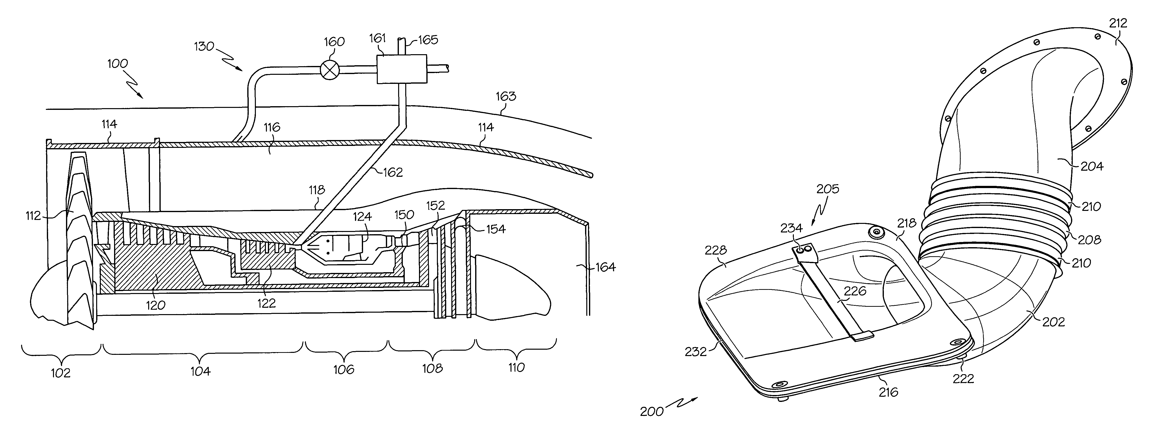
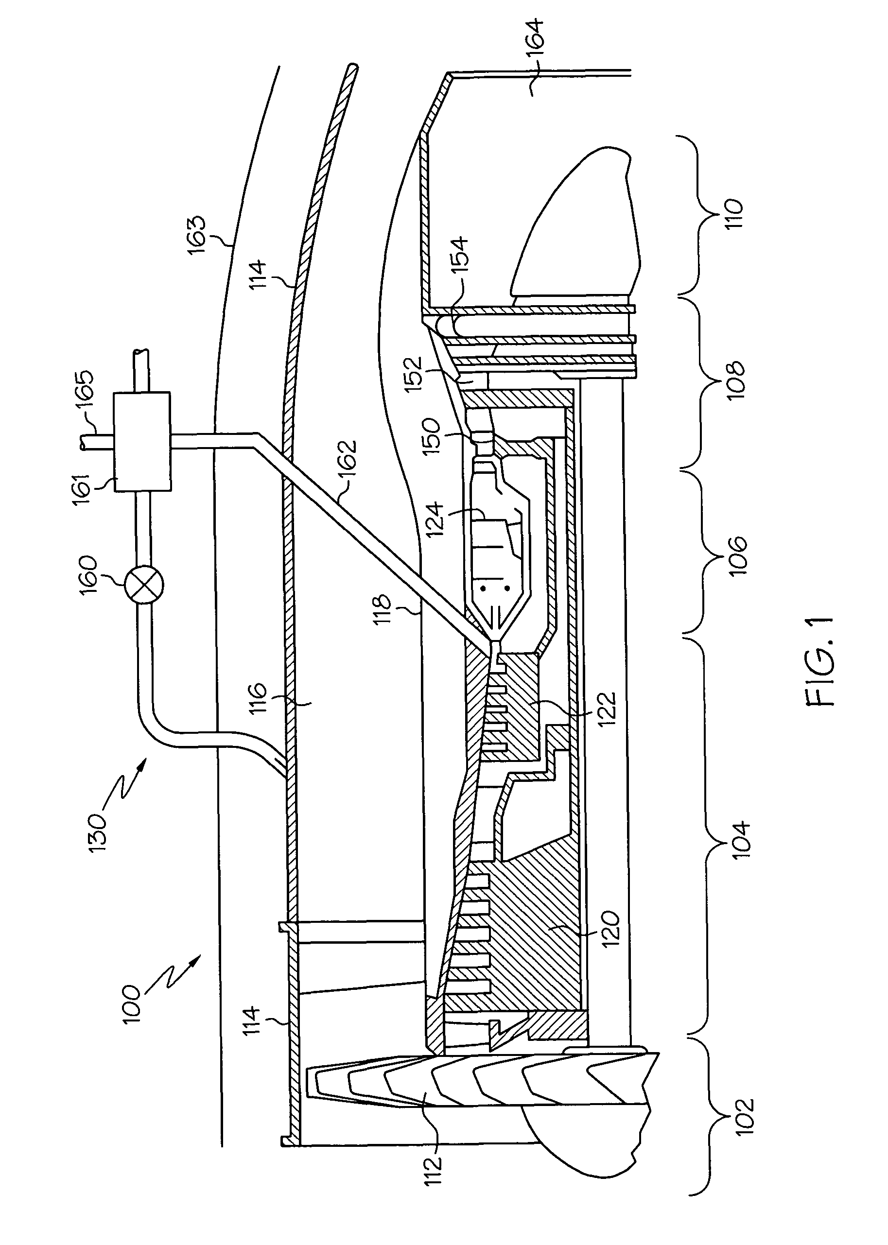
[0018]The embodiment disclosed herein is described in sufficient detail to enable those skilled in the art to practice the invention, and it is to be understood that other embodiments may be utilized and that logical mechanical changes may be made without departing from the scope of the present invention. Furthermore, it will be understood by one of skilled in the art that although the specific embodiment illustrated below is depicted and described as being implemented in an aircraft gas turbine engine bleed air system, it will be appreciated that it can be implemented in various other systems and environments, and can be u...


PUM


Abstract

A bleed air duct that preferably includes an inlet section configured to include a flush scoop and a louver. The louver is located and configured such that in the desired operating flow range of the duct, the fluid entering the flush scoop is disturbed and as a result creates a low pressure region downstream of the louver. The low pressure region substantially eliminates the generation of any pressure pulses and acoustic resonance also known as Helmholtz resonance.

Description

TECHNICAL FIELD[0001]The present invention relates to bleed air duct systems and, more particularly, to an inlet of the duct system, configured to minimize tonal resonance in the duct system.BACKGROUND[0002]A gas turbine engine may be used to supply power to various types of vehicles and systems. For example, gas turbine engines may be used to supply propulsion power to an aircraft. Many gas turbine engines include at least three major sections, a compressor section, a combustor section, and a turbine section. The compressor section receives a flow of intake air and raises the pressure of this air to a relatively high level. In a multi-spool (e.g., multi-shaft) engine, the compressor section may include two or more compressors. The compressed air from the compressor section then enters the combustor section, where a ring of fuel nozzles injects a steady stream of fuel. The injected fuel is ignited by a burner, which significantly increases the energy of the compressed air.[0003]The ...

Claims


Application Information

Patent Timeline
Patent Type & Authority Patents(United States)
IPC IPC(8): F02C6/04
CPCF01D17/105F02C9/18F02K3/06Y02T50/672Y02T50/60
Inventor HOOVER, ROBERTANDERSON, MORRISROMANO, ROBERTMENDOZA, JEFFJUDD, DANWEIR, DON
Owner HONEYWELL INT INC
Why Eureka
Try Eureka