Optical element, and illuminating optical device, display device and electronic device using the same

a technology of optical elements and illumination devices, applied in the direction of identification means, instruments, computing, etc., can solve the problems of affecting moire fringes, display devices using, user inconvenience, etc., and achieve the elimination of periodicity, high-quality display images or illumination, and the effect of eliminating periodicity

Active Publication Date: 2011-09-27
NEC LCD TECH CORP
View PDF13 Cites 7 Cited by
  • Summary
  • Abstract
  • Description
  • Claims
  • Application Information

AI Technical Summary

Benefits of technology

[0027]According to the configuration described above, light beams which pass through the periodic structure portions in which the phases of spatial frequency is different from each other are averaged. The effect of averaging light beams eliminates periodicity in the entire periodic structure portions. By eliminating the periodicity of an optical element (microlouver) in such a manner, production of Moire fringes caused by a phase difference in spatial frequency between the optical element, and a display panel or a lens sheet having periodicity can be reduced.
[0028]According to the present invention as described above, by averaging light beams, the periodicity of the optical element (microlouver) can be eliminated to control production of Moire fringes, thereby high-quality display images or illumination can be provided.

Problems solved by technology

However, in the case certain devices, such mobile phones, in which it is assumed that personal privacy is desired, the wide, viewable screen may sometimes allow unwanted third parties to view displayed information, which will be displeasing to the user.
Further, in the case of an information processing terminal used by an unspecified number of the general public, it is necessary to prevent other people from peeping at displayed information, when highly confidential information such as personal information is displayed.
However, display devices using the microlouver described above have the following problems.
The problem concerning Moire fringes arises not only between a display element and a microlouver, but when components having periodicity are stacked one on top of the other.

Method used


Image

  • Optical element, and illuminating optical device, display device and electronic device using the same
  • Optical element, and illuminating optical device, display device and electronic device using the same
  • Optical element, and illuminating optical device, display device and electronic device using the same

Examples


first exemplary embodiment

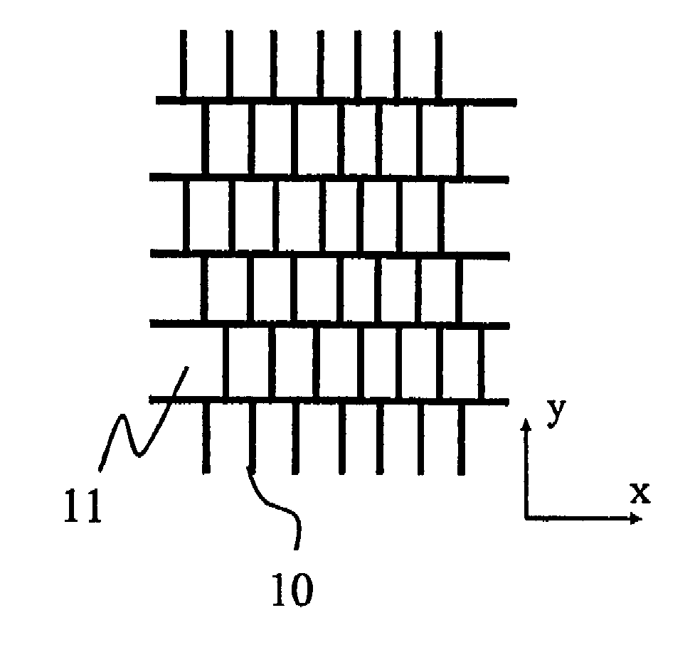
[0077]FIG. 9 is a schematic diagram illustrating a periodic structure of a microlouver of a first exemplary embodiment of an optical element according to the present invention. FIG. 10 is a cross-sectional view of the microlouver.

[0078]The microlouver of this exemplary embodiment, as shown in FIG. 10, is configured in a manner that is configured such that a periodic structure body, in which light absorption layer 10 and transparent layer 11 are alternately disposed, is sandwiched and held between two transparent substrates 12 and 13. The periodic structure body, as shown in FIG. 9, has a plurality of periodic structures 1 to 5. In each of periodic structures 1 to 5, a repetitive period PI in a portion composed of light absorption layer 10 and transparent layer 11 is the same. The period PI corresponds to a pitch P in a portion composed of light absorption layer 10 and transparent layer 11 shown in FIG. 10. Further, a width w1 and a thickness t1 of light absorption layer 10, and a wi...

second exemplary embodiment

[0084]FIG. 12 is a schematic diagram illustrating a periodic structure of a microlouver of a second exemplary embodiment according to the present invention. Also the microlouver of this exemplary embodiment is configured in a manner that is configured such that a periodic structure body, in which light absorption layer 10 and transparent layer 11 are alternately disposed, is sandwiched and held between two transparent substrates 12 and 13 as shown in FIG. 10, but the relationship among phases of spatial frequency of a plurality of periodic structures 1 to 5 constituting the periodic structure body is different from that of the first exemplary embodiment. In this exemplary embodiment, arrangement of the periodic structures having the phase of “0” and the periodic structures having the phase of “π” is determined based on progression generation rules or a random number.

[0085]The structure shown in FIG. 12 is a part of a periodic structure body in which arrangement of the periodic struc...

third exemplary embodiment

[0095]FIG. 15 is a schematic diagram illustrating a periodic structure of a microlouver of a third exemplary embodiment according to the present invention. Also the microlouver of this exemplary embodiment is configured in a manner that is configured such that a periodic structure body, in which light absorption layer 10 and transparent layer 11 are alternately disposed, is sandwiched and held between two transparent substrates 12 and 13 as shown in FIG. 10, but the relationship among phases of spatial frequency of a plurality of periodic structures 1 to 5 constituting the periodic structure body is different from that of the first exemplary embodiment. In this exemplary embodiment, the periodic structure body is configured by using four kinds of periodic structure: a periodic structure having a phase of “0”, a periodic structure having a phase of “π / 4”, a periodic structure having a phase of “π / 2”, and a periodic structure having a phase of “π”.

[0096]In the configuration shown in F...


PUM

PropertyMeasurementUnit
distanceaaaaaaaaaa
distanceaaaaaaaaaa
distanceaaaaaaaaaa

Abstract

A microlouver includes a periodic structure in which a transparent layer and a light absorption layer are alternately disposed with a constant, repetitive period. The range of the exit direction of a light beam passing through the transparent layer is restricted by the light absorption layer. The periodic structure includes a periodic structure portion divided in the direction that intersects the direction in which the transparent layer and the light absorption layer are repeatedly disposed. In the periodic structure portion, between the periodic structures adjacent to each other, there is a difference of 180 degree in the phase of spatial frequency of each periodic structure.

Description

[0001]This application is based upon and claims the benefit of priority from Japanese Patent Application No. 2006-267978 filed in Japan Patent Office on Sep. 29, 2006, the contents of which are hereby incorporated by reference.BACKGROUND OF THE INVENTION[0002](1) Field of the Invention[0003]The present invention relates to an optical element called “microlouver” by which the range of the exit direction of a transmitted light beam is restricted. Further, the present invention relates to an illuminating optical device and a display device as represented by a liquid crystal display (LCD) or a plasma display using such an optical element.[0004](2) Description of the Related Art[0005]Liquid crystal displays are used as display devices for various electronic devices such as mobile phones, Personal Digital Assistance (PDA), ATM (Automatic Teller Machine) or personal computers, and recently there are practical uses for liquid crystal display that have a wide, viewable area.[0006]A liquid cr...

Claims


Application Information

Patent Timeline
Patent Type & Authority Patents(United States)
IPC IPC(8): G09G3/34G02B5/00G02B5/02G02F1/1335G09F9/00
CPCG02B5/003G02B5/201G02F1/1323G02F1/133606G02F2001/133607G02F1/133607G02F1/1335
Inventor MIMURA, KOJISUMIYOSHI, KEN
Owner NEC LCD TECH CORP
Why Eureka
Try Eureka