
Torque-limiting fastener driver

a technology of fastener driver and torque limiter, which is applied in the direction of wrenches, medical science, surgery, etc., can solve the problems of affecting the operation efficiency of the operation, the danger of damaging the driver tip or the fastener head, and the fastener driver for driving very small fasteners. achieve the effect of sufficient siz

Active Publication Date: 2011-10-04
BIOMET CV
View PDF48 Cites 24 Cited by
  • Summary
  • Abstract
  • Description
  • Claims
  • Application Information

AI Technical Summary

Benefits of technology

"The invention is a fastener driver for driving bone fasteners into bone. It includes a handle and a removable driver shaft that is attached to the handle. The driver shaft is made of metal and has a unique design that allows it to bend and twist elastically within a certain range of forces. This design provides a tactile feedback to the user and also includes a visual indicator to indicate the degree of twist. The driver shaft has a frangible segment that breaks at a predetermined location if the applied torque exceeds its yield strength. This prevents any harmful pieces from being left in the patient's body. The technical effects of this invention include improved control and accuracy when driving bone fasteners and a safer surgical procedure."

Problems solved by technology

During some bone plating procedures, surgeons may have difficulty aligning the fastener driver with the bone plate fastener due to limited access, visualization, etc.
If the driver tip is not properly engaged with the fastener head while attempting to drive the fastener into bone, there is danger of damaging the driver tip or the fastener head.
Fastener drivers for driving very small fasteners, such as used for attaching small, low profile bone plates to bone, are especially susceptible to this type of damage.
During a plating procedure, the surgeon may use the fastener driver for several fasteners, resulting in accumulated wear of the driver tip.
Further, fastener drivers are known which limit the torque that can be applied to the fastener that is being driven.

Method used


Image

  • Torque-limiting fastener driver
  • Torque-limiting fastener driver
  • Torque-limiting fastener driver

Examples


Embodiment Construction

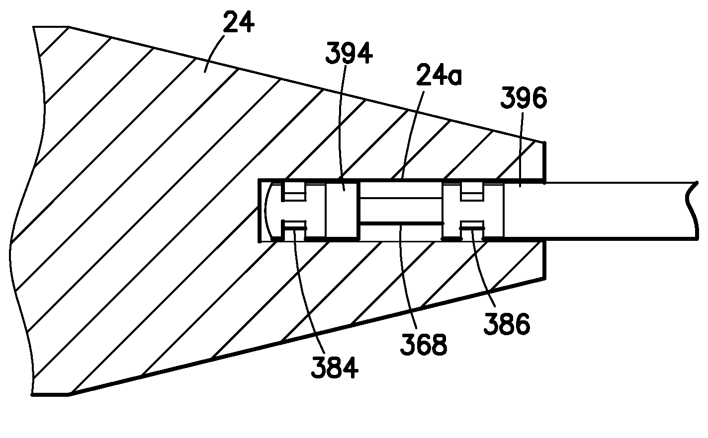
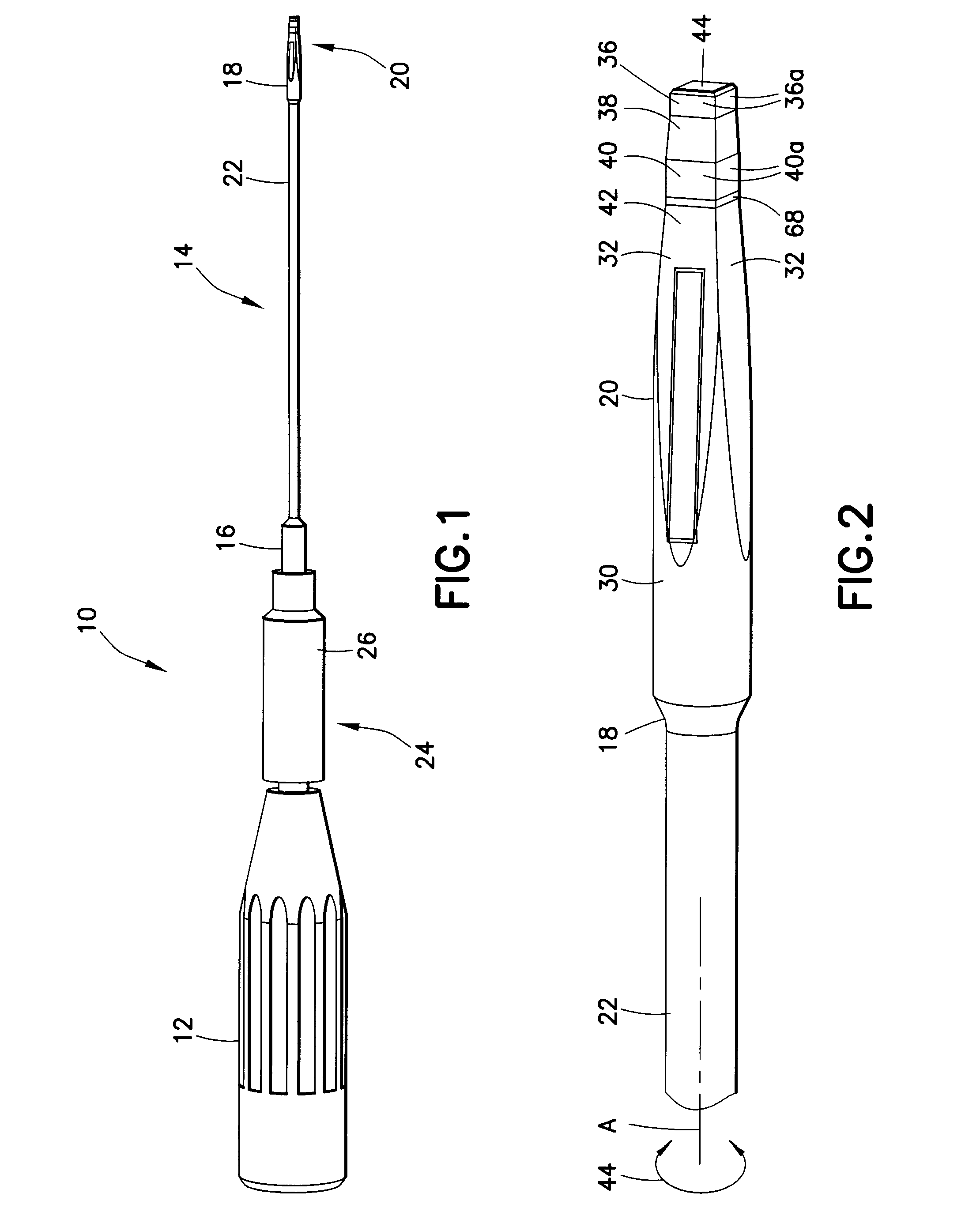
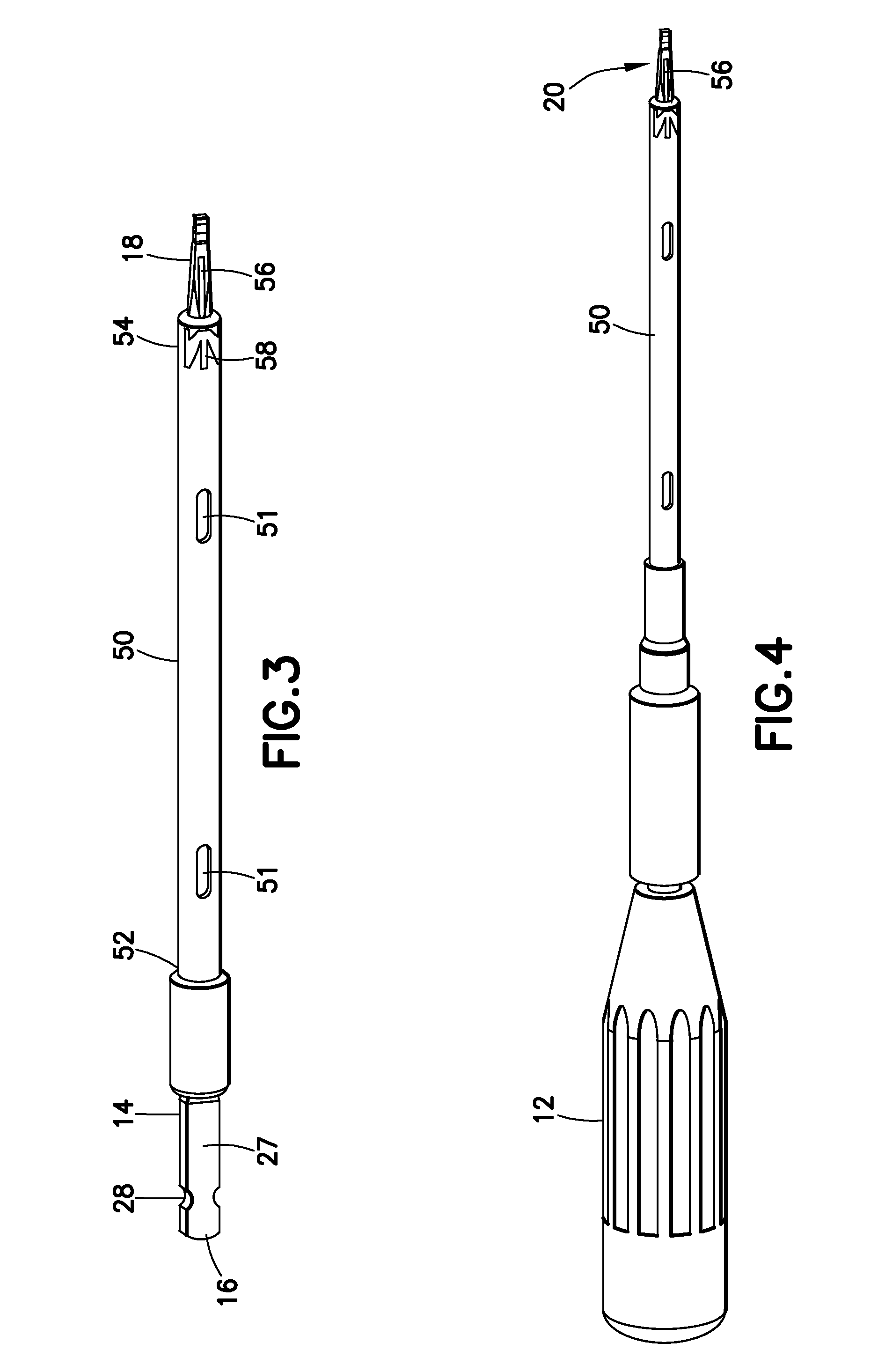
[0022]Turning now to FIGS. 1 and 2, a torque-limiting fastener driver 10 for driving a bone fastener into bone is shown. The driver in the embodiment shown is particularly designed to drive small bone screws into low profile plates, such as to stabilize fractures in the hand. It is understood that the driver can be modified as necessary to drive bone fasteners for other orthopedic applications.

[0023]The driver 10 includes a handle 12 and a driver shaft 14 rotatably fixed relative to the handle. The driver shaft 14 is a once-piece metal component having a proximal end 16, a distal end 18 configured into a driver tip 20 for driving engagement with a head of a bone fastener, and a middle portion 22 between the proximal and distal ends. In a preferred embodiment, the shaft 14 is made from 440 stainless steel having a hardness of at least 48 RC. This material is chosen for its high tensile strength.

[0024]The proximal end 16 of the driver shaft 14 is preferably removably coupled to the ha...


PUM


Abstract

A torque-limiting fastener driver for driving a bone fastener into bone includes a handle supporting a driver shaft. The driver shaft includes limited components which are designed to provide feedback to a user regarding the applied torsional force. In addition, the driver shaft is designed to controllably fail before any potential uncontrolled failure of the distal driving tip. This prevents application of too much torque and controlled design of the shape and size of the failed components.

Description

FIELD OF THE INVENTION[0001]This invention relates broadly to surgical instruments. More particularly, this invention relates to instruments for driving fasteners in orthopedic applications.STATE OF THE ART[0002]During some bone plating procedures, surgeons may have difficulty aligning the fastener driver with the bone plate fastener due to limited access, visualization, etc. If the driver tip is not properly engaged with the fastener head while attempting to drive the fastener into bone, there is danger of damaging the driver tip or the fastener head. Fastener drivers for driving very small fasteners, such as used for attaching small, low profile bone plates to bone, are especially susceptible to this type of damage.[0003]During a plating procedure, the surgeon may use the fastener driver for several fasteners, resulting in accumulated wear of the driver tip. Therefore, it is also desirable to provide a sterile, low cost driver that may be discarded after use in one surgical proced...

Claims


Application Information

Patent Timeline
Patent Type & Authority Patents(United States)
IPC IPC(8): B25B23/153B25B15/02A61B17/58
CPCA61B17/888B25B15/02B25B23/0042B25B23/1415B25B23/1427A61B2019/301A61B2090/031
Inventor SIXTO, JR., ROBERTKORTENBACH, JUERGEN A.CASTANEDA, JAVIER E.AMPUERO, EDUARDO A.CASTANEDA, ALFREDOMARQUART, JOEL G.
Owner BIOMET CV
Learn More