Programmable logic controller, control unit, and method for calculating lifespan of unit

A programming logic and control unit technology, which is applied in the direction of program control, program control, electrical program control, etc. in the sequence/logic controller, can solve problems such as system stop, and achieve the effect of preventing cost increase

Inactive Publication Date: 2019-03-26
MITSUBISHI ELECTRIC CORP
View PDF11 Cites 0 Cited by
  • Summary
  • Abstract
  • Description
  • Claims
  • Application Information

AI Technical Summary

Problems solved by technology

If the above-mentioned management is not carried out, there will be a problem that the syst...

Method used


Image

  • Programmable logic controller, control unit, and method for calculating lifespan of unit
  • Programmable logic controller, control unit, and method for calculating lifespan of unit
  • Programmable logic controller, control unit, and method for calculating lifespan of unit

Examples


Embodiment approach

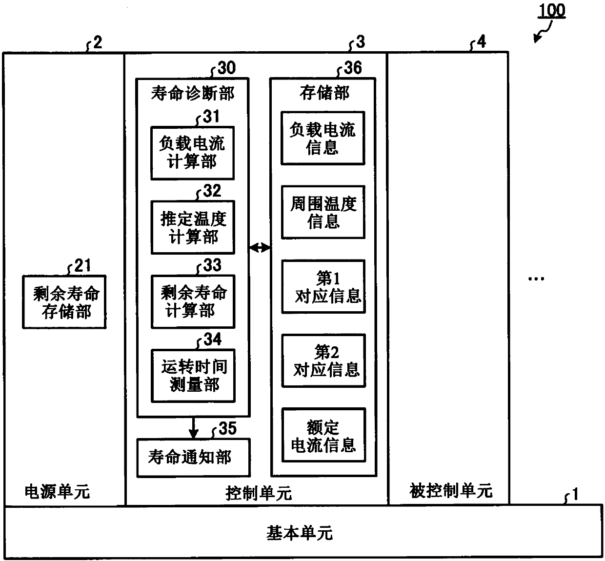
[0018] figure 1 It is a figure which shows the structural example of the programmable logic controller (PLC) which concerns on embodiment of this invention. PLC 100 according to this embodiment is realized by combining a plurality of units. Specifically, the PLC 100 is composed of various units such as a base unit 1 , a power supply unit 2 , a control unit 3 , and a controlled unit 4 . In addition, the PLC 100 has one or more controlled units 4 .

[0019] The basic unit 1 electrically connects the power supply unit 2 , the control unit 3 and the controlled unit 4 . The power supply unit 2 supplies power to the control unit 3 and the controlled unit 4 via the base unit 1 . The control unit 3 controls the controlled unit 4 . The controlled unit 4 is various units that operate according to instructions from the control unit 3 . The controlled unit 4 is an input unit that inputs signals from sensors installed in production equipment and equipment, an output unit that outputs ...


PUM


Abstract

The present invention pertains to a programmable logic controller (100) that is formed of a control unit (3) and a power supply unit (2) to which a lifespan-limited component is mounted, wherein the power supply unit (2) is provided with a residual lifespan storage unit (21) which retains residual lifespan information representing the residual lifespan of the power supply unit (2), and the controlunit (3) is provided with: a load current calculation unit (31) for calculating a load current of the programmable logic controller (100); an estimated temperature calculation unit (32) whereby the programmable logic controller (100) calculates an estimated value of the temperature of the lifespan-limited component in operation on the basis of the load current and ambient temperature informationacquired from a user; and a residual lifespan calculation unit (33) which updates the residual lifespan information on the basis of the estimated value and the operating time of the programmable logiccontroller (100).

Description

technical field [0001] The present invention relates to a programmable logic controller having a function of diagnosing the life of parts, a control unit and a life calculation method of the unit. Background technique [0002] A programmable logic controller (PLC: Programmable Logic Controller, hereinafter referred to as PLC) is generally composed of a plurality of units. The power supply unit, one of the units constituting the PLC, is equipped with life-saving components such as electrolytic capacitors, and the power supply unit itself has a life span. In order to maintain the PLC system, it is necessary to manage the replacement timing of units such as power supply units equipped with life-saving components. If the above-mentioned management is not performed, there arises a problem that the system suddenly stops when the life-spanning components mounted on the unit reach the end of life. [0003] In view of the above-mentioned problems, Patent Document 1 describes an inv...

Claims


Application Information

Patent Timeline
IPC IPC(8): G05B19/05
CPCG05B19/05Y02P90/02G05B2219/14G05B19/058G05B23/0283G05B19/0428G05B19/4065G05B19/40938G05B19/4183
Inventor 志水义信丰永匡利
Owner MITSUBISHI ELECTRIC CORP
Why Eureka
Try Eureka