Respiratory monitoring

a technology for respiratory monitoring and monitoring devices, applied in the field of respiratory monitoring, can solve the problems of large power consumption, high cost of capnographers, and limited use in hospitals and other controlled environments, and achieve the effect of prolonging the useful life of said patient interfa

Active Publication Date: 2011-10-04
JPMORGAN CHASE BANK NA
View PDF211 Cites 623 Cited by
  • Summary
  • Abstract
  • Description
  • Claims
  • Application Information

AI Technical Summary

Benefits of technology

[0013]In some embodiments, the generating a signal comprises generating a signal indicative of a carbon dioxide concentration of said gas and / or generating a signal indicative of a respiratory rate of said patient. The providing said signal can include wirelessly transmitting the signal. In other embodiments, the method also includes controlling the transfer of said gas to a selected one of two or more sensors located within said patient interface. In one embodiment, controlling the transfer of said gas extends the useful life of said patient interface.

Problems solved by technology

Capnographers are typically expensive, relatively large, and consume a large amount of power.
Thus, their use is generally limited to hospitals and other controlled environments.

Method used


Image

  • Respiratory monitoring
  • Respiratory monitoring
  • Respiratory monitoring

Examples


Embodiment Construction

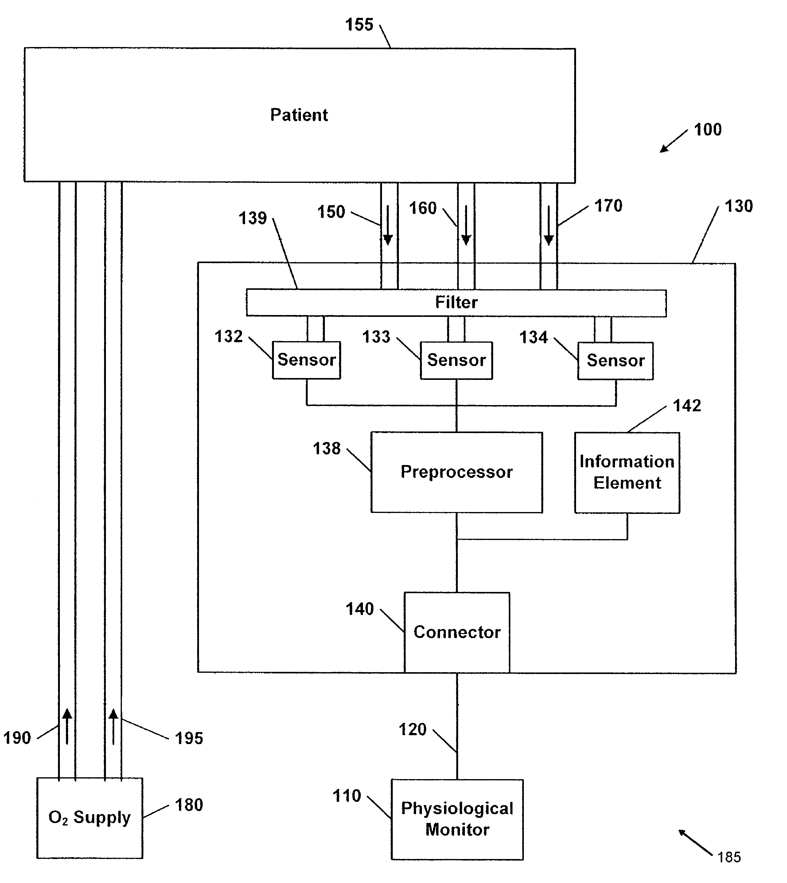
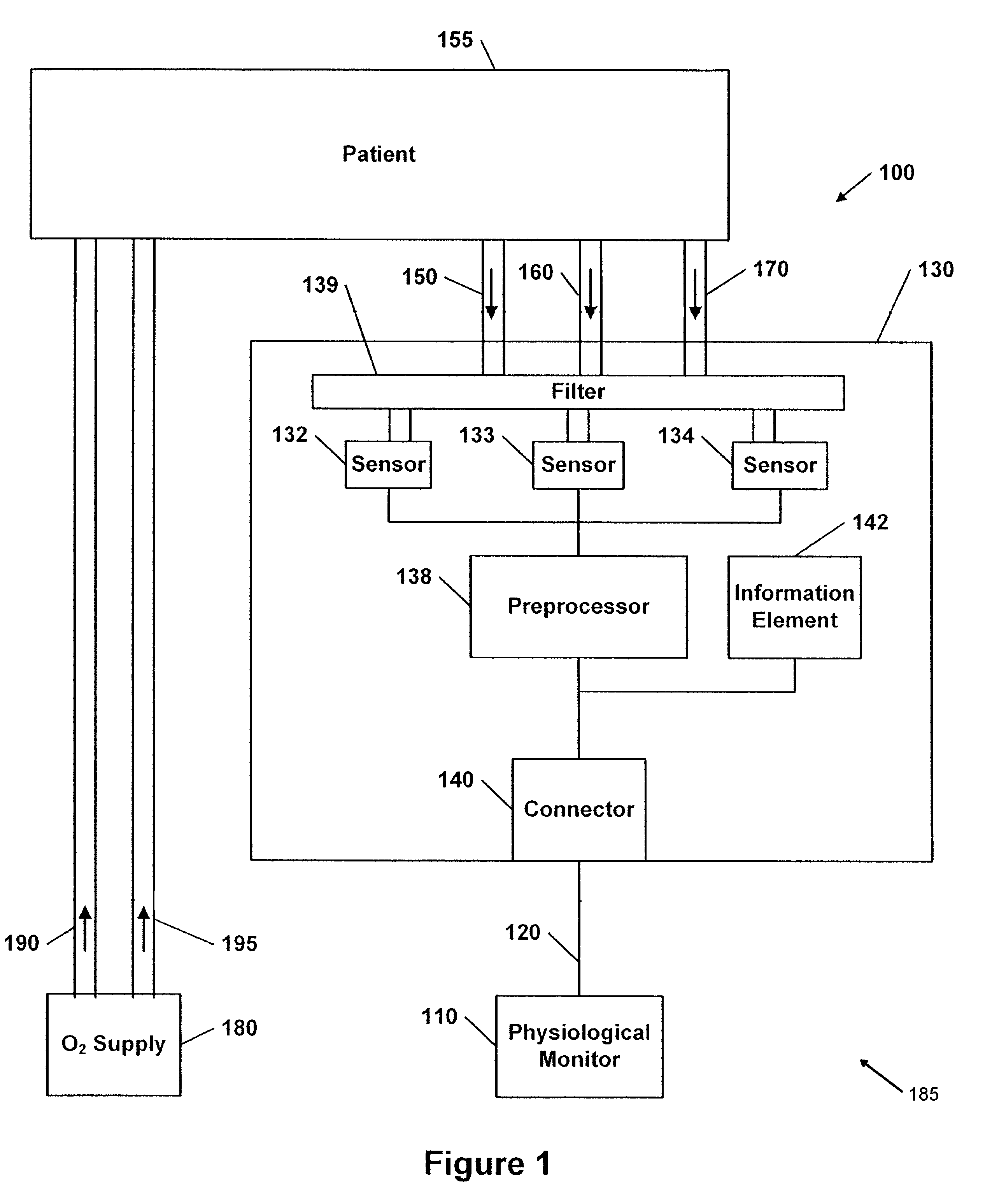
[0019]FIG. 1 illustrates a respiratory monitoring system 100 in accordance with one embodiment of the present invention. The respiratory monitoring system 100 generally includes a physiological monitor 110 coupled to or in communication with a patient interface 185 via a communication link 120. The patient interface 185 is coupled to a patient 155. Exhaled breath from the patient 155 is received by the patient interface 185. Oxygen from an oxygen supply 180 can also be provided to the patient 155 with the patient interface 185.

[0020]The patient interface 185 of the respiratory monitoring system 100 generally includes two nasal cannulae 150, 160, e.g., tubes, for insertion into or placement adjacent the nostrils of the patient 155. The patient interface 185 may also optionally include an oral cannula tube 170 for insertion into or placement adjacent the patient's mouth. The tubes 150, 160, and 170 are configured to transfer or guide gases exhaled from the patient 155 to a carbon diod...


PUM


Abstract

A patient interface in accordance with one embodiment of the present invention is configured to be at least partially carried by a patient and to receive gas exhaled by the patient. The patient interface includes first and second cannula tubes each having a first end and a second end, the first ends are configured to be inserted into the nostrils of a patient, the first and second cannula tubes are configured to direct exhaled gas from the patient from the first ends to said second ends. The patient interface also includes first and second sensors positioned near the second ends, and the first and second sensors are configured to provide first and second signals based upon the gas, wherein the first and second signals are indicative of a physiological parameter of the patient. The patient interface also includes a communications link configured to provide the signal to a physiological monitor.

Description

CROSS-REFERENCE TO RELATED APPLICATIONS[0001]This application claims priority from U.S. Provisional No. 60 / 809,882, filed May 31, 2006, which is incorporated by reference herein.BACKGROUND[0002]1. Field of the Invention[0003]The invention relates generally to systems, devices, and methods for monitoring a patient's respiratory system and health, including capnographers and other devices that deliver oxygen to a patient.[0004]2. Description of the Related Art[0005]Capnographers have been widely used for measuring concentration of carbon dioxide in a patient's exhaled breath and monitoring respiratory rate. The amount of carbon dioxide in a person's breath can indicate the overall efficiency of the cardio-pulmonary system and quality of breathing. For example, the concentration of carbon dioxide can indicate shallow breathing and poor oxygen intake. Thus, capnographers are used in hospitals and other medical institutions for monitoring the condition of a patient's respiratory system, ...

Claims


Application Information

Patent Timeline
Patent Type & Authority Patents(United States)
IPC IPC(8): A61M11/00
CPCA61M16/0672A61B5/0836A61B5/097A61B5/6819A61B5/682A61M16/0666A61M16/10A61B5/0004A61B5/0816A61B5/6822A61M2230/432A61M2202/0208A61M2205/18A61M2205/3561A61M2205/581A61M2205/583A61M2230/42A61M2230/435A61M16/085A61M16/1065
Inventor AL-ALI, AMMARDIAB, MOHAMED K.
Owner JPMORGAN CHASE BANK NA
Why Eureka
Try Eureka