Two-substance atomizing nozzle

a technology of atomizing nozzles and substances, which is applied in the direction of gaseous fuel burners, combustion types, combustion processes, etc., can solve the problems of considerable affecting the operation of the reaction vessel, the size of the reaction vessel and its production costs, and the inability to meet the requirements of the production process

Active Publication Date: 2011-10-04
WURZ DIETER
View PDF18 Cites 15 Cited by
  • Summary
  • Abstract
  • Description
  • Claims
  • Application Information

AI Technical Summary

Benefits of technology

[0009]By providing the annular gap that surrounds the outlet opening and is subjected to atomizing gas, for example air or water vapor, a liquid film on the wall of the nozzle mouth, in particular the divergent outlet portion, is drawn out into a very thin liquid lamella, which breaks down into small drops. In this way, the formation of large drops from liquid films on the wall in the nozzle outlet region can be prevented or reduced to an acceptable degree, and at the same time the fine drop spectrum in the jet core can be maintained, without the compressed gas consumption of the two-substance nozzle or the associated self-energy requirement having to be increased for this. Experimental studies conducted by the inventors have shown that provision of an annular gap allows the maximum drop size to be reduced to about a third for the same expenditure of energy. This may be considered to be a minor effect. However, it must be borne in mind that the volume of a drop of a diameter reduced by a factor of 3 is only one twenty seventh of that of the large drop. Without going here into the interrelated aspects that are known to all, it should be clear to a person skilled in the art that this gives rise to considerable advantages with respect to the required overall volume of evaporative coolers or sorption systems, for example for flue-gas purification. With the additional annular-gap atomization, a much finer drop spectrum can therefore be produced with the same expenditure of energy. The amount of air passed through the annular gap is advantageously 10% to 40% of the total amount of air that is atomized. In process engineering installations in which atomized substances are introduced into vessels or channels that are at approximately the same pressure as the surroundings (1 bar), the total pressure of the air in the annular gap is advantageously 1.5 bar to 2.5 bar absolute. The total pressure of the air in the annular gap should advantageously be at such a level that, when expansion takes place to the pressure level in the vessel, approximately the speed of sound is reached.
[0034]For example, a first plane, counting from the liquid inlet, may have left-turning inlet bores, the second plane right-turning inlet bores and the third plane again left-turning inlet bores. The opposing swirling directions have the effect of producing very pronounced shearing layers in the mixing chamber, contributing to the formation of particularly fine drops.

Problems solved by technology

For example, the size of a reaction vessel and its production costs depend considerably on the average drop size.
However, it is often by no means adequate for the average drop size to be below a certain limit value.
Even a few significantly larger drops can lead to considerable operational malfunctions.
This is the case in particular whenever the drops do not evaporate quickly enough on account of their size, so that drops or even pasty particles are deposited in downstream components, for example on filter fabrichoses or fan blades, and lead to operational malfunctions due to encrustations or corrosion.
A basic problem with such nozzles results from the fact that the walls of the mixing chamber 7 are wetted with liquid.

Method used


Image

  • Two-substance atomizing nozzle
  • Two-substance atomizing nozzle
  • Two-substance atomizing nozzle

Examples


Embodiment Construction

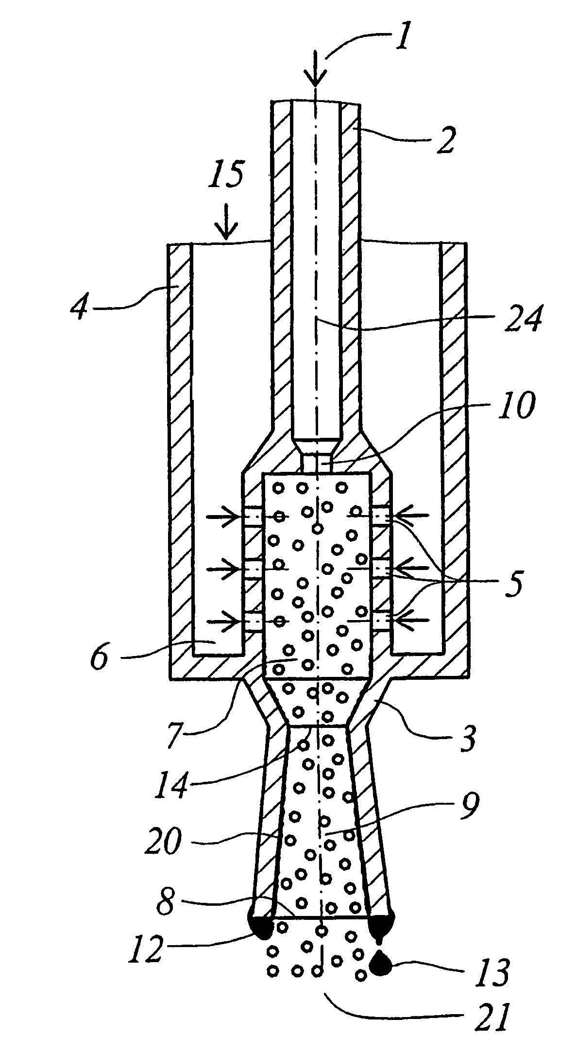
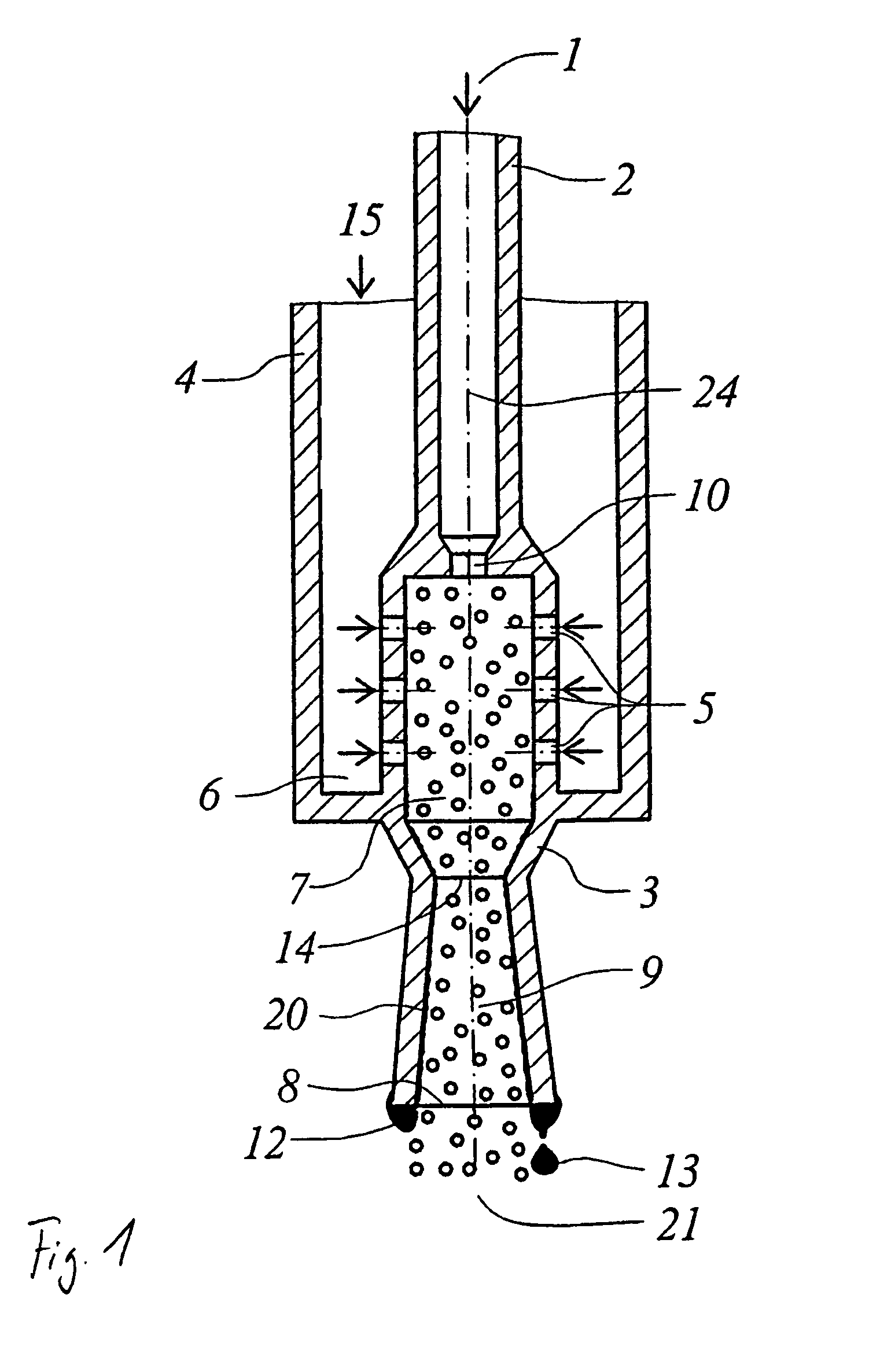
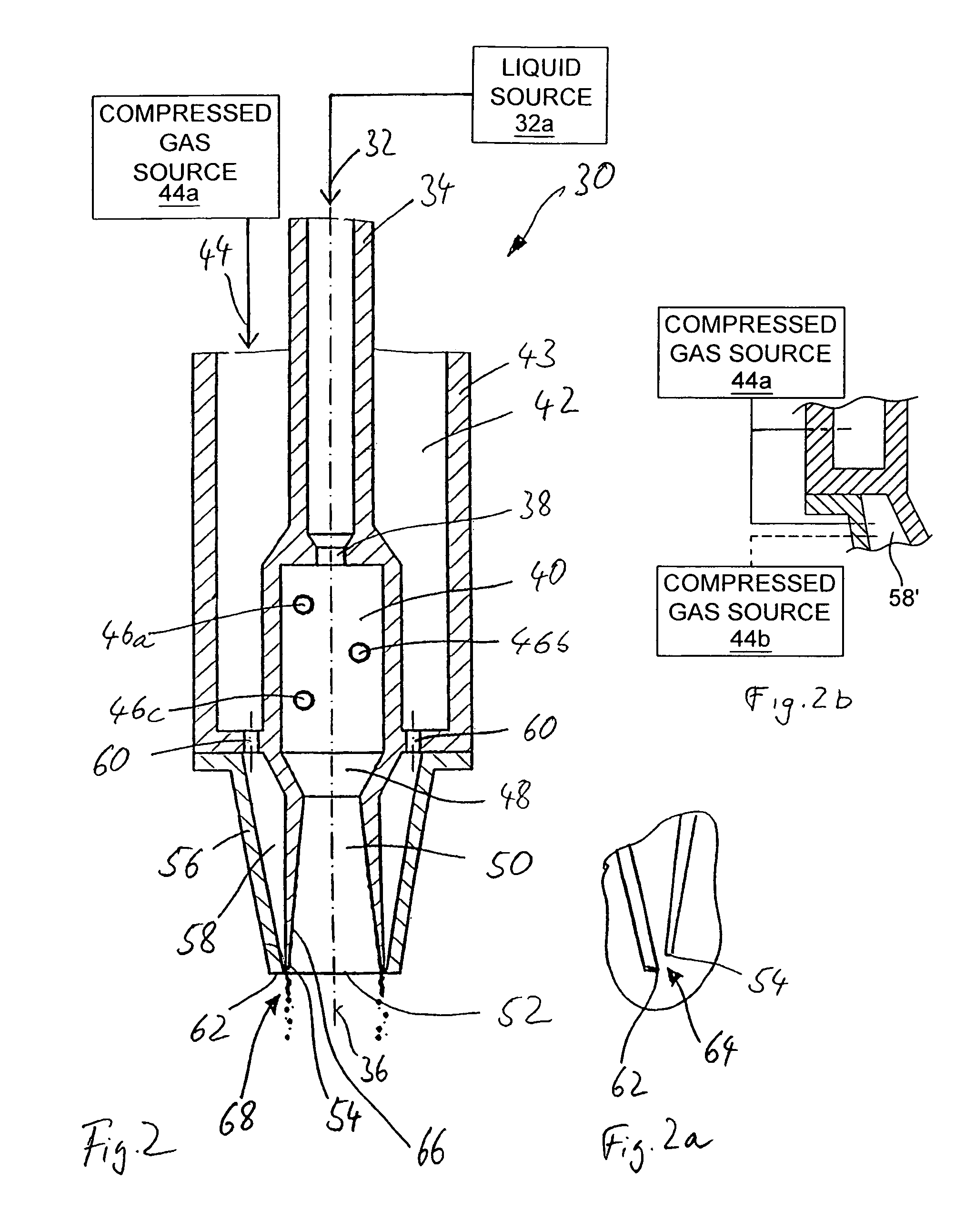
[0045]The sectional view of FIG. 2 shows a two-substance atomizing nozzle 30 according to the invention, according to a first preferred embodiment. The two-substance atomizing nozzle 30 according to the invention is constructed in a way similar to the known nozzle according to FIG. 1, at least as far as the introduction of the liquid and the compressed gas into the mixing chamber and the shaping of the nozzle adjoining the mixing chamber are concerned. A liquid to be atomized is supplied in the direction of an arrow 32 from a liquid source 32a by way of an inner lance tube 34, which extends parallel to a center longitudinal axis 36 of the nozzle 30, and passes to a liquid inlet 38, which has a reduced cross section in comparison with the tube 34. After passing the liquid inlet 38, the liquid then passes in the form of a liquid jet extending concentrically with respect to the center longitudinal axis 36 into the cylindrical mixing chamber 40 arranged concentrically with respect to th...


PUM


Abstract

An atomizing nozzle for two substances, which is used for spraying a liquid with the aid of a compressed gas, is provided. The atomizing nozzle includes a mixing chamber, a liquid inlet that extends into the mixing chamber, a compressed gas inlet which extends into the mixing chamber, and an outlet located downstream from the mixing chamber. An annular gap is provided which surrounds the outlet and discharges compressed gas at a high speed. The atomizing nozzle is used for purifying flue gas.

Description

FIELD OF THE INVENTION[0001]The invention relates to a two-substance atomizing nozzle for spraying a liquid with the aid of a compressed gas, comprising a mixing chamber, a liquid inlet opening out into the mixing chamber, a compressed gas inlet opening out into the mixing chamber and an outlet opening downstream of the mixing chamber.BACKGROUND OF THE INVENTION[0002]In many process engineering installations, liquids are distributed in a gas. In such cases, it is often of decisive importance that the liquid is sprayed in drops that are as fine as possible. The finer the drops, the greater the specific surface area of the drops. This can give rise to considerable process engineering advantages. For example, the size of a reaction vessel and its production costs depend considerably on the average drop size. However, it is often by no means adequate for the average drop size to be below a certain limit value. Even a few significantly larger drops can lead to considerable operational ma...

Claims


Application Information

Patent Timeline
Patent Type & Authority Patents(United States)
IPC IPC(8): F23D11/16
CPCB05B7/0458
Inventor WURZ, DIETERHARTIG, STEFAN
Owner WURZ DIETER
Why Eureka
Try Eureka