
Purification of carbon dioxide

a technology of carbon dioxide and purification, applied in the field of purification of carbon dioxide, can solve the problems of reducing the heating and economic value of gas, oxygen presence, and no details regarding how the general idea might be implemented

Active Publication Date: 2008-07-24
AIR PROD & CHEM INC
View PDF14 Cites 119 Cited by
  • Summary
  • Abstract
  • Description
  • Claims
  • Application Information

AI Technical Summary

Benefits of technology

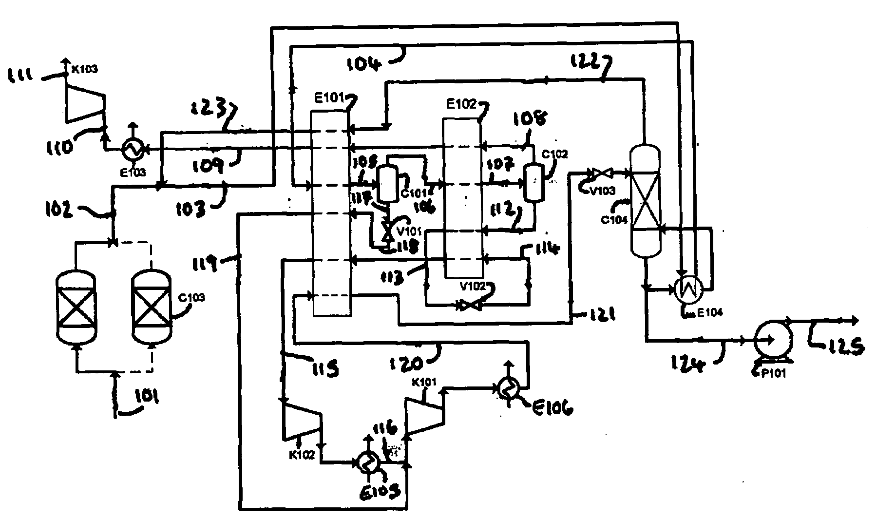
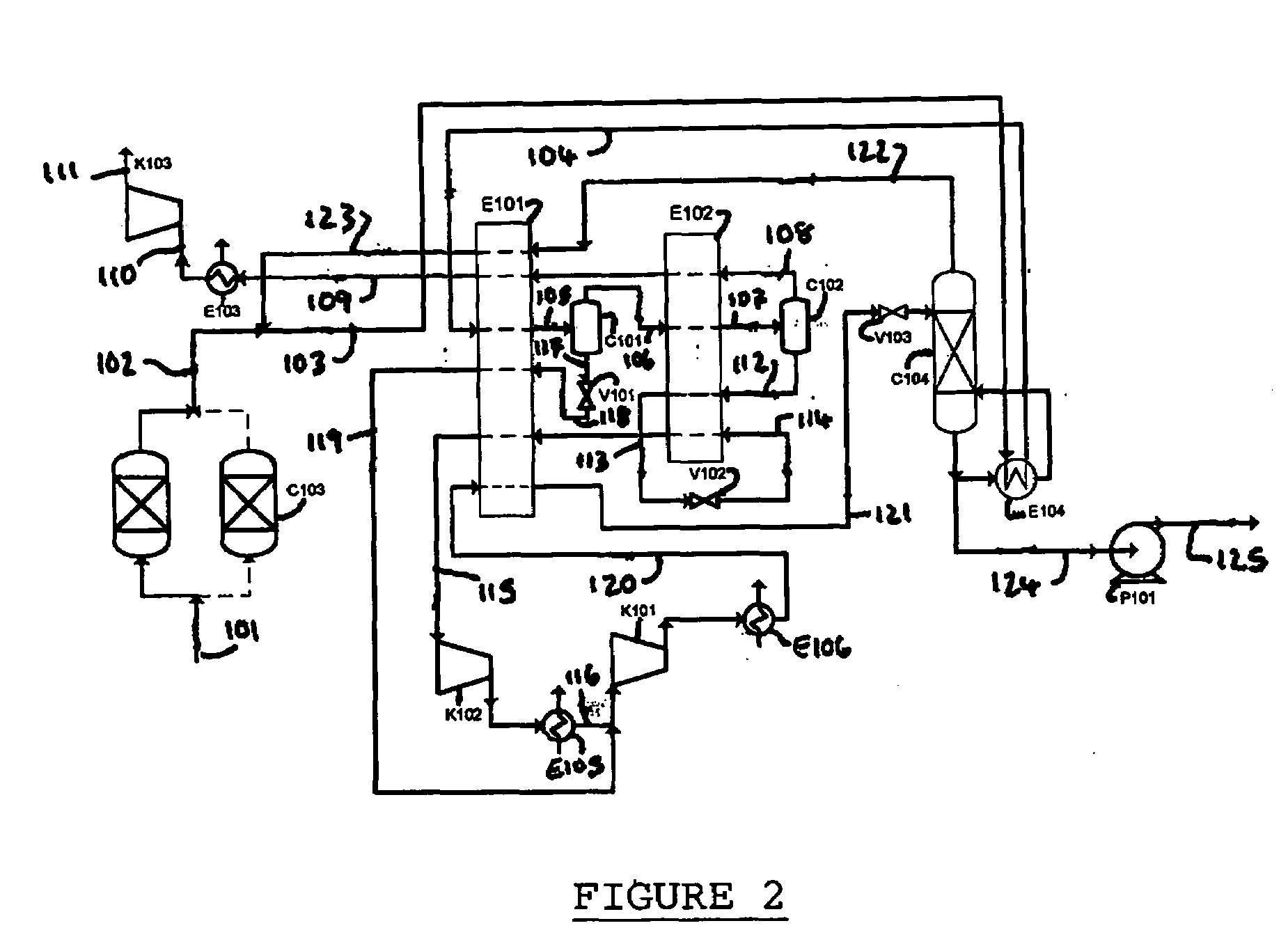
[0246]In the embodiment exemplified in FIG. 2, column C104 operates at a pressure of about 30 bar and the product carbon dioxide liquid is pressurized to above the critical pressure for carbon dioxide. However, one advantage of the present invention is that column C104 could be operated at different pressures to suit the required delivery pressure of the liquid carbon dioxide. For example, the column could be operated at a pressure from about 15 bar to about 30 bar to produce liquid carbon dioxide at a pressure suitable for transportation in a road tanker or at a pressure from about 5 bar to 10 bar to produce liquid carbon dioxide at a pressure suitable for transportation in a tanker ship without further pressure adjustment.
[0247]The embodiment depicted in FIG. 3 is similar to the embodiment depicted in FIG. 2. The same reference numerals have been used in FIG. 3 as in FIG. 2 to denote the common features between the two embodiments. The following is a discussion of only the additional features of the embodiment in FIG. 3.
[0248]A stream 124 of carbon dioxide-enriched bottoms liquid at a pressure of about 30 bar removed from column C104 is flashed in flash vessel C106 to produce carbon dioxide vapor and liquid carbon dioxide at a pressure of about 7 bar.
[0249]It should be noted that the carbon dioxide bottoms liquid may be flashed to any pressure below the operating pressure of the column and above the triple point pressure for carbon dioxide depending on the required delivery pressure of the liquid carbon dioxide for transportation.
[0250]A stream 125 of liquid carbon dioxide is removed for transportation or distribution. A stream 126 of carbon dioxide vapor is warmed by indirect heat exchange in the heat exchangers E102, E101 to produce a stream 127 of carbon dioxide gas. Stream 127 is compressed in compressor K105 to produce compressed carbon dioxide gas at a pressure of about 17.6 bar which, after removal of heat of compression by indirect heat exchange in heat exchanger E107 forming stream 128, is combined with stream 119 (which is also at a pressure of about 17.6 bar in the embodiment of FIG. 3) to produce impure gaseous carbon dioxide. The impure gaseous carbon dioxide is combined with stream 116 to produce the impure carbon dioxide gas.
[0251]Carbon dioxide compressors K101, K102 and K105 are provided by an integrally geared machine with multiple radial stages. K101 has three or four stages, optionally with intercooling between some stages although not within the last two stages because of the fact that the discharge pressure is above the critical pressure. K102 is one or two stages on the same machine with an intercooler and an aftercooler. K105 is further stages of the same integrally geared machine.

Problems solved by technology

The presence of oxygen may present problems when the carbon dioxide is intended for use in enhanced oil or gas recovery operations due to the possibility of oxidation causing corrosion problems in downhole equipment.
However, no details regarding how the general idea might be implemented were disclosed.
The presence of the carbon dioxide in the stream decreases the heating and economic value of the gas.

Method used


Image

  • Purification of carbon dioxide
  • Purification of carbon dioxide
  • Purification of carbon dioxide

Examples


example 1

[0253]A computer simulation has been carried out using commercially available simulation software (Aspen Plus Version 2004.1) in which the process depicted in FIG. 2 is integrated with an oxyfuel combustion process in a power generation plant. A heat and mass balance table for the simulation is provided in Table 2.

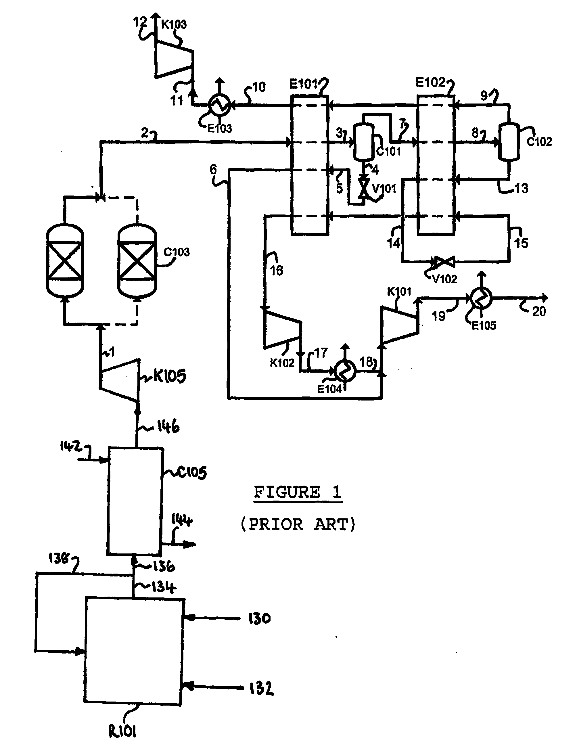
[0254]The simulation achieved a carbon dioxide purity level of about 99.98 mol % with a carbon dioxide recovery of about 87.7%. The power consumption for this process is about 349.9 kWh / tonne (carbon dioxide captured) which is less than the power consumption (354.7 kWh / tonne) for the process in FIG. 1. These power figures include the power consumption of an associated air separation unit.

[0255]The carbon dioxide recovery can be increased to about 98% by using a membrane separation unit to recover carbon dioxide and oxygen from the carbon dioxide-lean gas in stream 109. The delivery temperature of supercritical carbon dioxide discharging from pump P101 is 0.7° C. This cold ...

example 2

[0256]A computer simulation (Aspen Plus Version 2004.1) has been carried out in which the process depicted in FIG. 2 is integrated with a hydrogen PSA system (not shown). The off gas from the PSA system is compressed to 30 bar to form a stream 101 of compressed off gas which is fed to the process. A heat and mass balance table for the simulation is provided in Table 3.

[0257]The simulation indicates that the carbon monoxide level can be reduced to about 100 ppm.

TABLE 3Stream Number101102103104105106107108109110Temperature° C.20.0020.0019.321.57−28.71−28.71−53.91−53.9119.00300.00Pressurebar a3030.003030303030303030Flowkg / s54.5954.5667.1367.1367.1329.1329.139.599.599.59CompositionCO2mol %71.607171.680075.142775.142775.142755.451955.451923.139823.139823.1398N2mol %0.99510.99620.91200.91200.91201.59821.59822.70452.70452.7045Armol %0.16830.16840.15640.15640.15640.27220.27220.45700.45700.4570H2mol %21.862521.884818.850018.850018.850034.141034.141059.439559.439559.4395H2Omol %0.10170.00000....

example 3

[0258]A computer simulation (Aspen Plus Version 2004.1) has been carried out in which the process depicted in FIG. 3 is integrated with an oxyfuel combustion process in a power generation plant. A heat and mass balance table for the simulation is provided in Table 4.

[0259]This embodiment produces liquid carbon dioxide at a pressure of about 7 bar at a power consumption of about 361.8 kWh / tonne (carbon dioxide captured) which is surprisingly lower than the power consumption (about 375 kWh / tonne) for the production of liquid carbon dioxide from a mass transfer separation column operating at about 7 bar.

TABLE 4Stream Number101102103104105106107108109110Temperature° C.24.8324.8323.41−1.73−36.26−36.26−54.00−54.0018.97300.00Pressurebar a3030.003030303030303030Flowkg / s140.4964.46177.80177.80177.8064.4664.4642.1742.1742.17CompositionCO2mol %72.763372.865175.877675.877675.877645.361245.361224.796124.796124.7961N2mol %18.969418.995916.806916.806916.806938.214338.214352.647452.647452.6474Armol...


PUM

PropertyMeasurementUnit
Pressureaaaaaaaaaa
Pressureaaaaaaaaaa
Pressureaaaaaaaaaa

Abstract

Impure carbon dioxide (“CO2”) comprising a first contaminant selected from the group consisting of oxygen (“O2”) and carbon monoxide (“CO”) is purified by separating expanded impure carbon dioxide liquid in a mass transfer separation column system. The impure carbon dioxide may be derived from, for example, flue gas from an oxyfuel combustion process or waste gas from a hydrogen (“H2”) PSA system.

Description

BACKGROUND OF THE INVENTION[0001]The present invention relates to a method and apparatus for purifying impure liquid carbon dioxide (“CO2”) comprising a first contaminant selected from the group consisting of oxygen (“O2”) and carbon monoxide (“CO”). The process and apparatus have particular application in the recovery of carbon dioxide from waste carbon dioxide gas, for example flue gas from an oxyfuel combustion process or waste gas from a hydrogen (“H2”) pressure swing absorption (“PSA”) process.[0002]There is an urgent need to develop new processes for production of electrical energy from fossil fuels, carbonaceous fuels or hydrocarbon fuels with capture of carbon dioxide. The new processes should ideally be more efficient and cost effective than existing processes. Oxyfuel combustion processes are being considered in this context.[0003]In oxyfuel combustion, a fuel is combusted in pure oxygen with optional recycle of cooled flue gas or steam or water to moderate the flame tempe...

Claims


Application Information

Patent Timeline
IPC IPC(8): B01D15/08C01B32/50
CPCB01D53/002Y10S62/928B01D2256/16C01B31/20F25J3/0266F25J2200/02F25J2200/40F25J2200/70F25J2200/76F25J2200/78F25J2205/02F25J2205/04F25J2210/04F25J2210/70F25J2215/04F25J2220/82F25J2240/90F25J2245/02F25J2270/02F25J2270/88Y02C10/12Y10S62/926B01D53/047C01B32/50Y02C20/40Y02P20/151B01D53/00F25J3/08
Inventor WHITE, VINCENTALLAM, RODNEY JOHN
Owner AIR PROD & CHEM INC
Learn More