

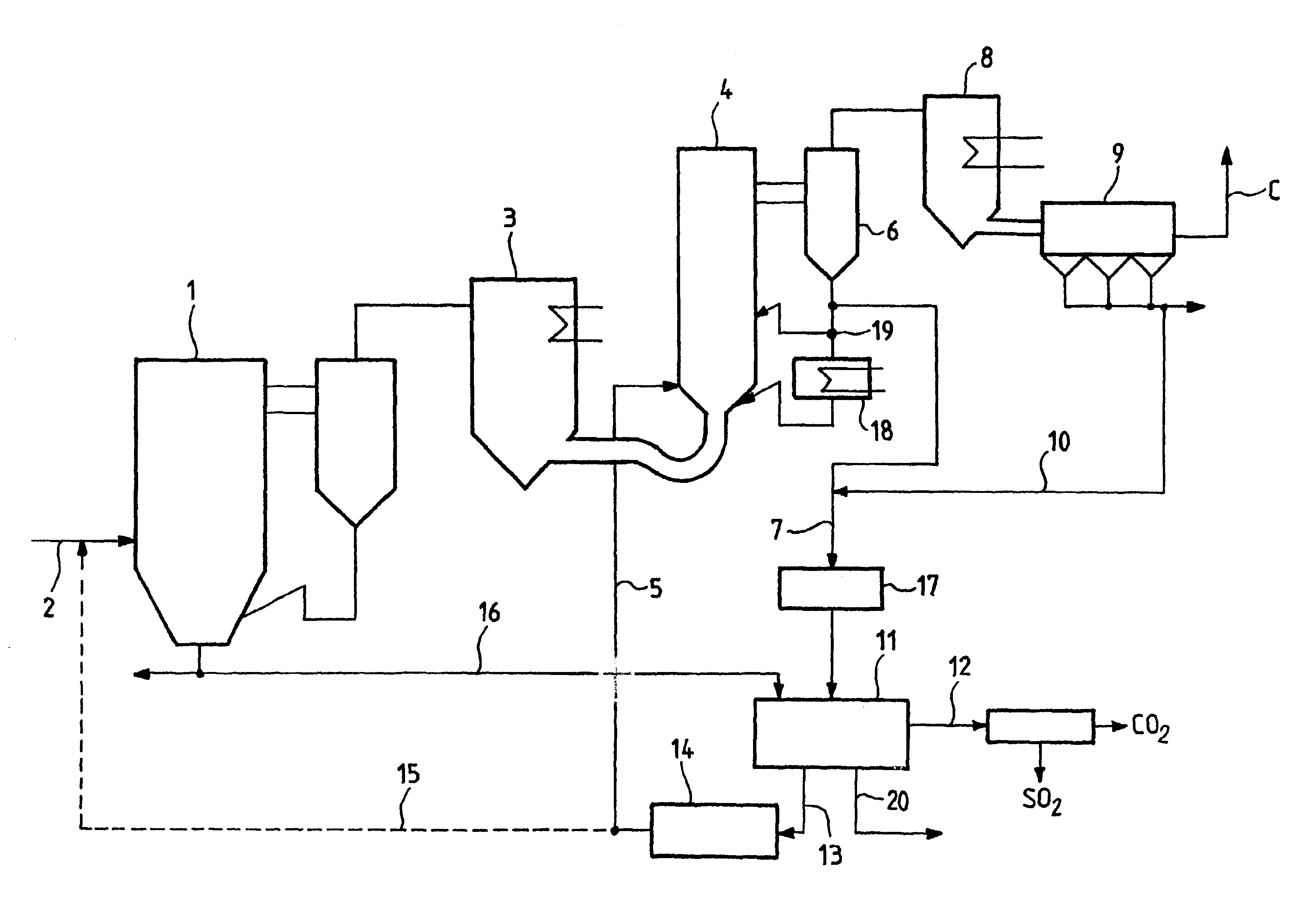
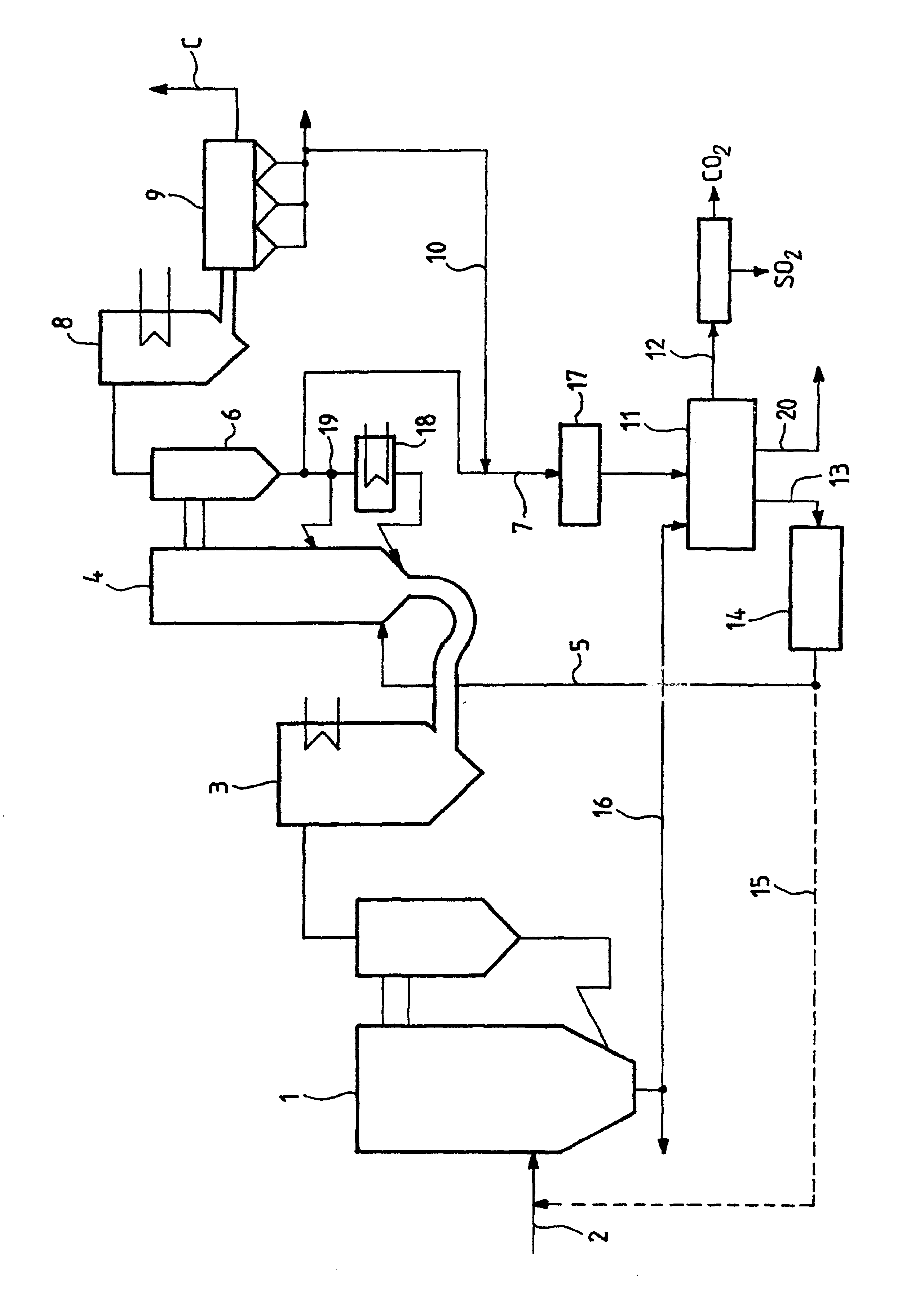
Method of simultaneously reducing CO2 and SO2 emissions in a combustion installation
a technology of co2 and so2 emissions and combustion installations, which is applied in the direction of emission prevention, combustion types, separation processes, etc., can solve the problems of desulfurizing the flue gas with calcium carbonate injection, and achieve the effect of reducing carbon dioxide emissions and sulfur dioxide emissions
- Summary
- Abstract
- Description
- Claims
- Application Information
AI Technical Summary
Benefits of technology
Problems solved by technology
Method used
Image

Examples
Embodiment Construction
Combustion of carbon-containing matter such as fossil fuels or waste produces gaseous emissions of CO.sub.2 and of SO.sub.2. In known manner, combustion in a fluidized bed, for example, makes it possible to obtain effective desulfurization of the flue gases when an absorbant based on calcium such as calcium carbonate is injected into the hearth, such desulfurization taking place by means of the following reactions:
CaCO.sub.3 ->CaO+CO.sub.2 (decarbonization)
CaO+SO.sub.2 +1 / 2O.sub.2 ->CaSO.sub.4
Such fluidized bed combustion thus suffers from the drawback that it generates CO.sub.2 in addition to the CO.sub.2 that results from burning the organic carbon of the fuel.
It is also known that CO.sub.2 is a "greenhouse" gas whose concentration in the atmosphere is increasing, which could contribute to global warming. A second drawback of such fluidized bed combustion lies in the quantity of ash produced that is rich in CaSO.sub.4 and in CaO, which could limit the use of such ash.
The invention...
PUM
| Property | Measurement | Unit |
|---|---|---|
| temperature | aaaaa | aaaaa |
| temperature | aaaaa | aaaaa |
| temperature | aaaaa | aaaaa |
Abstract
Description
Claims
Application Information