Printer with recording paper leading edge storage unit

a technology of leading edge storage unit and printing paper, which is applied in the field of printing, can solve the problems of printer becoming large, printer becoming large, printer becoming large,

Active Publication Date: 2011-10-04
CITIZEN WATCH CO LTD
View PDF14 Cites 2 Cited by
  • Summary
  • Abstract
  • Description
  • Claims
  • Application Information

AI Technical Summary

Benefits of technology

[0024]In contrast, in the first embodiment of the present invention, the recording paper storage unit is formed using at least a part of the periphery of the rolled recording paper and, thereby, a recording paper set-aside space can be reserved. In the second embodiment of the present invention, the head and the ejection slot are provided on both sides across the rolled paper holder to allow a part of the space required for a distance between the head and the recording paper storage unit to be used for storing the rolled paper holder. This configuration improves the space efficiency in the printer and makes the printer compact.
[0027]Because the recording paper storage unit provides a space in which a rolled paper is held, this configuration allows the printer housing to shield the recording paper, which is being printed and temporarily set aside, from the external environment and, thereby, prevents dirt and dust from accumulating on the surface of the recording paper being printed, thus ensuring the print quality.
[0033]The printer of the present invention further comprises, on the ejection path, a recording paper cutting unit that cuts the recording paper; and an ejection slot through which the recording paper is ejected externally of the housing of the printer. Below this recording paper cutting unit, the printer further comprises a chip storage unit in which chips of the recording paper cut by the recording paper cutting unit are stored. This configuration stores the chips of the recording paper, cut by the recording paper cutting unit, in the chip storage unit within the printer to prevent the chips from being leaked from the printer.
[0034]In the second embodiment of the present invention, one of the wall surfaces of the recording paper storage unit of the printer can be formed by a dividing plate provided adjacent to at least a part of the periphery of the rolled paper holder. In the configuration in which the head and the ink ribbon are provided at the back of the side opposite to the front wall across the rolled paper holder, the dividing plate is provided in a position that is adjacent to the periphery of the rolled paper holder and that is on the side opposed to the front wall. Providing this dividing plate prevents the recording paper, unrolled from the rolled paper holder, from coming into contact with recording paper rolled on the rolled paper holder and thereby from the printed paper surface of the recording paper from being damaged or smeared.
[0036]The printer of the present invention, which reciprocates a rolled recording paper repeatedly for printing thereon, can reserve the recording paper set-aside space without separately reserving said space and, thereby, reserve the recording paper storage unit set-aside space without making the printer larger.

Problems solved by technology

This requirement creates a problem that the recording paper storage unit becomes vertically or horizontally large according to the diameter of this cylindrical body and, as a result, the printer becomes large.
This requirement creates a problem that the recording paper storage unit becomes large horizontally according to the length or width of this box-shaped body and, as a result, the printer becomes large.
For this reason, in whichever way the recording paper is stored, reserving the space for installing the recording paper storage unit within the printer housing requires a larger printer housing and so the problem is that the printer becomes large.
A still another problem is that, because the length of an image on a recording paper is limited by the length of a recording paper stored in the recording paper storage unit, the image cannot printed in a print area longer than the recording paper stored in the recording paper storage unit.

Method used


Image

  • Printer with recording paper leading edge storage unit
  • Printer with recording paper leading edge storage unit
  • Printer with recording paper leading edge storage unit

Examples


first embodiment

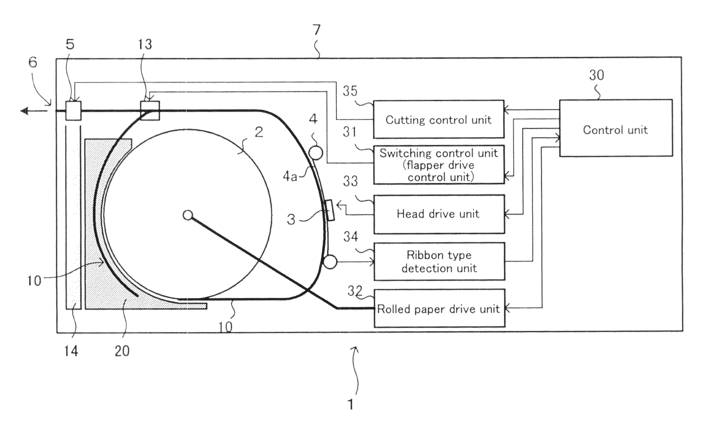
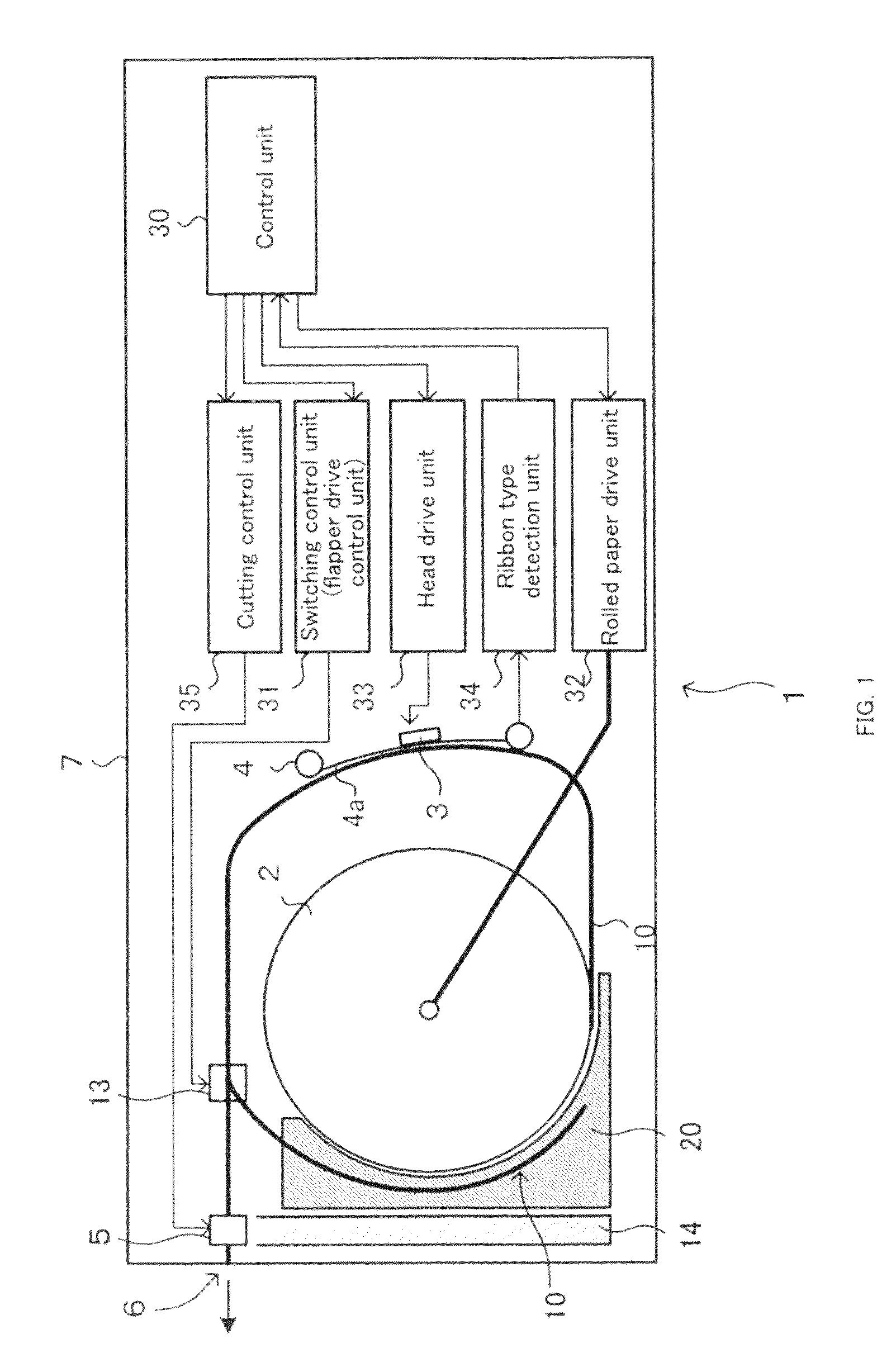
[0064]In the present invention shown in FIG. 1, the printer 1 uses the peripheral part of the rolled paper holder 2 as a recording paper storage unit 12 and uses that part as a storage space where the recording paper is temporarily set aside. In FIG. 1, the recording paper storage unit 12 is indicated by the shaded part. This recording paper storage unit 12 is created using a space in the peripheral part of the rolled paper holder 2, with the storage space formed by a gap between at least a part of the whole periphery and the inside wall of the printer. Normally, the peripheral part of the rolled paper holder has a space for storing the rolled paper and for unrolling and feeding the unrolled paper. Because the diameter of the periphery of the rolled paper holder is normally large enough to have a margin so that the peripheral part of the rolled paper does not contact the inside wall of the printer even when the diameter of this rolled paper is the maximum, an extra space is provided...

second embodiment

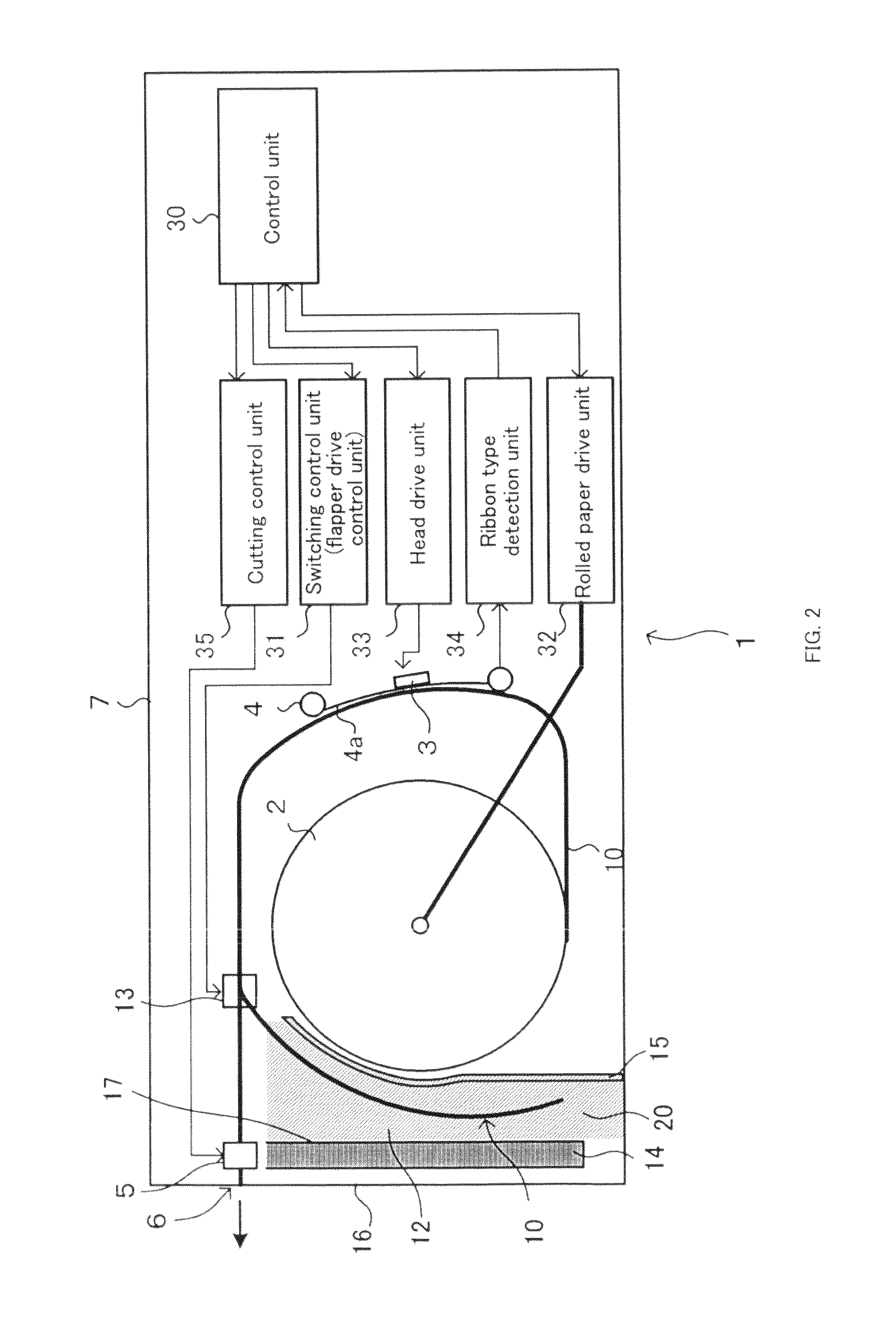
[0067]In the present invention shown in FIG. 2, a printer 1 has a recording paper storage unit 12 in the space between a rolled paper holder 2 and a front wall 16 through which a recording paper is ejected, and a recording paper 10 unrolled from the rolled paper holder 2 is temporarily set aside in this recording paper storage unit 12. In FIG. 2, a storage space 20 of the recording paper storage unit 12 is indicated by the shaded part.

[0068]This recording paper storage unit 12 uses the space between the rolled paper holder 2 and the front wall 16, through which the recording paper is ejected, to form a storage space.

[0069]The storage space of the recording paper storage unit 12 may have a configuration in which its border is determined by partition plates or a configuration in which the border is determined, not by partition plates, but by a member present in the space between the rolled paper holder 2 and the front wall 16.

[0070]In the configuration where the border of the storage ...


PUM

PropertyMeasurementUnit
storage lengthaaaaaaaaaa
colorsaaaaaaaaaa
coloraaaaaaaaaa

Abstract

A printer, which prints by repeatedly reciprocating a rolled recording paper and ejects a printed recording paper, has therein a recording paper storage unit in which the recording paper is temporarily stored. The recording paper storage unit has a configuration formed by at least a part of the periphery of the rolled recording paper or a configuration provided in a space between the rolled paper holder and an ejection slot. This configuration eliminates the need for separately providing a configuration in which a recording paper is set aside when printing a long sheet of printed material and, at the same time, makes the printer smaller.

Description

FIELD OF THE INVENTION[0001]The present invention relates to a printer that prints different colors on the same paper by reciprocating a rolled recording paper under the head to repeat printing on a recording paper multiple times.RELATED ART[0002]A multi-color printer for use in color printing uses three primary colors (yellow, magenta, and cyan) or four colors including black. One of such multi-color printers that are known is a printer that prints different colors on the same paper by repeating printing multiple times with a rolled recording paper reciprocating (For example, see Patent Document 1).[0003]To print on a recording paper, fed from the feed roller, with the use of the head, the printer disclosed in Patent Document 1 stores the recording paper, on which one color is printed with the use of one color head, in the recording paper storage unit. To print the next color, the printer rolls back the recording paper stored in this recording paper storage unit, passes the recordi...

Claims


Application Information

Patent Timeline
Patent Type & Authority Patents(United States)
IPC IPC(8): B41J2/32B65H29/60B41J15/04B41J2/325
CPCB41J11/70B41J15/042B65H29/20B65H29/58B65H2301/51256B65H2403/942B65H2404/6111B65H2404/632B65H2801/15
Inventor TAKAHASHI, AKIRATAGUCHI, YUICHIINOKUCHI, YUTAKA
Owner CITIZEN WATCH CO LTD
Why Eureka
Try Eureka