PLL with loop bandwidth calibration circuit

a calibration circuit and loop technology, applied in the direction of electrical equipment, pulse automatic control, etc., can solve the problems of increasing phase errors and suppressing modulation messages, and achieve the effect of low spur and quantization errors

Inactive Publication Date: 2011-10-04
MEDIATEK INC
View PDF2 Cites 29 Cited by
  • Summary
  • Abstract
  • Description
  • Claims
  • Application Information

AI Technical Summary

Benefits of technology

[0005]The present invention proposes a fractional-N PLL, which uses a linear PFD in a proportional path and a bang-bang PFD in an integral path. The PLL has advantages from using not only analog filters to achieve low spur and quantization error but also scalable digital filters.
[0008]The invention provides a loop bandwidth calibration technique for a DCO-based fractional-N PLL. The PLL has a linear PFD in a proportional path and a bang-bang PFD in an integral path. Calibrations work in a pure digital domain and 1 KHz resolution is achieved by the closed loop operation. Analysis showed that the architecture had both advantages of a type I and a type II loop filter, such as low jitter peaking and zero static phase error thereby, validating the effectiveness of the disclosed technique.

Problems solved by technology

A lower loop bandwidth, on the other hand, will suppress modulation messages and increase phase errors.

Method used


Image

  • PLL with loop bandwidth calibration circuit
  • PLL with loop bandwidth calibration circuit
  • PLL with loop bandwidth calibration circuit

Examples


Embodiment Construction

[0016]The following description is of the best-contemplated mode of carrying out the invention. This description is made for the purpose of illustrating the general principles of the invention and should not be taken in a limiting sense. The scope of the invention is best determined by reference to the appended claims.

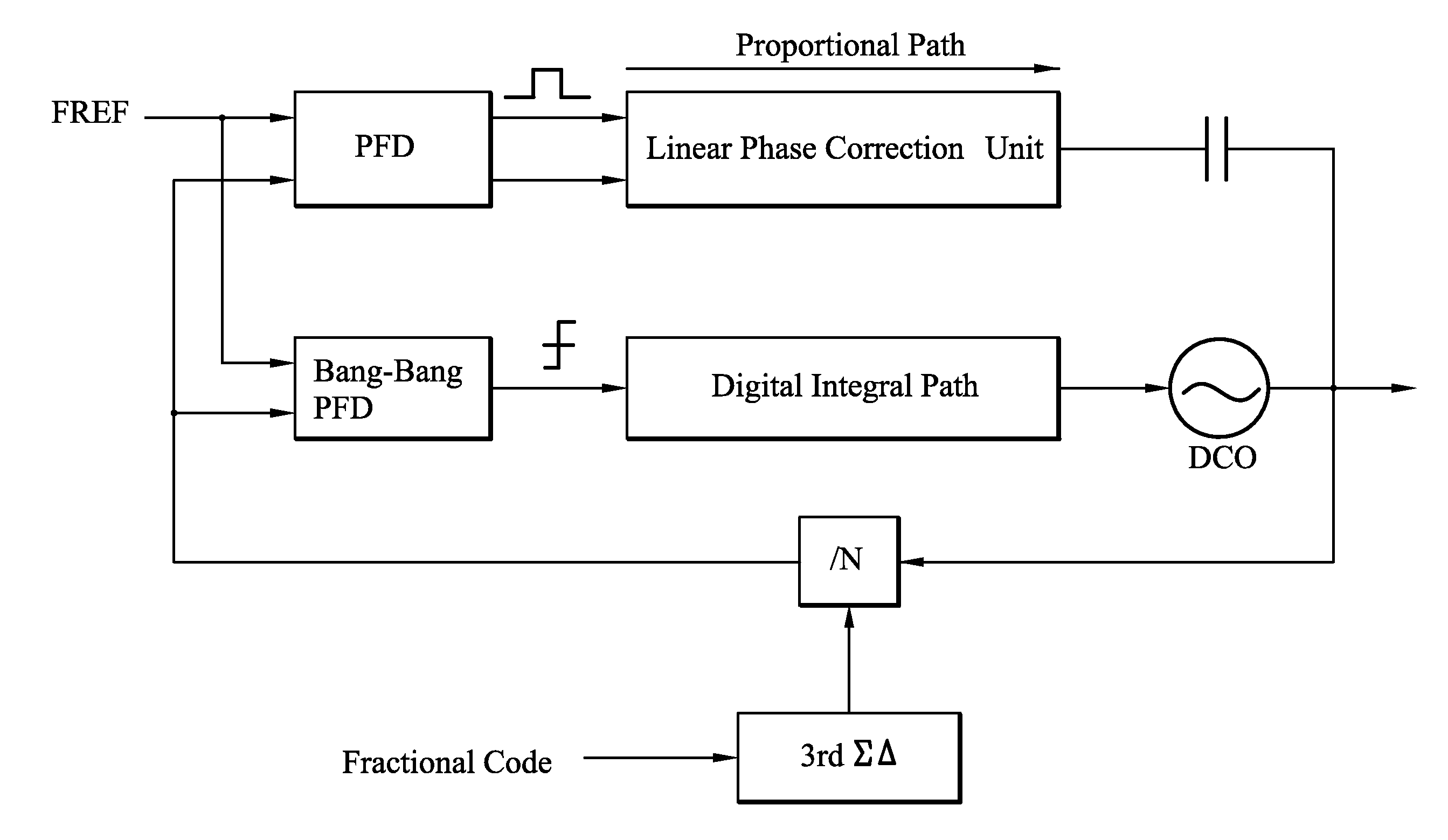
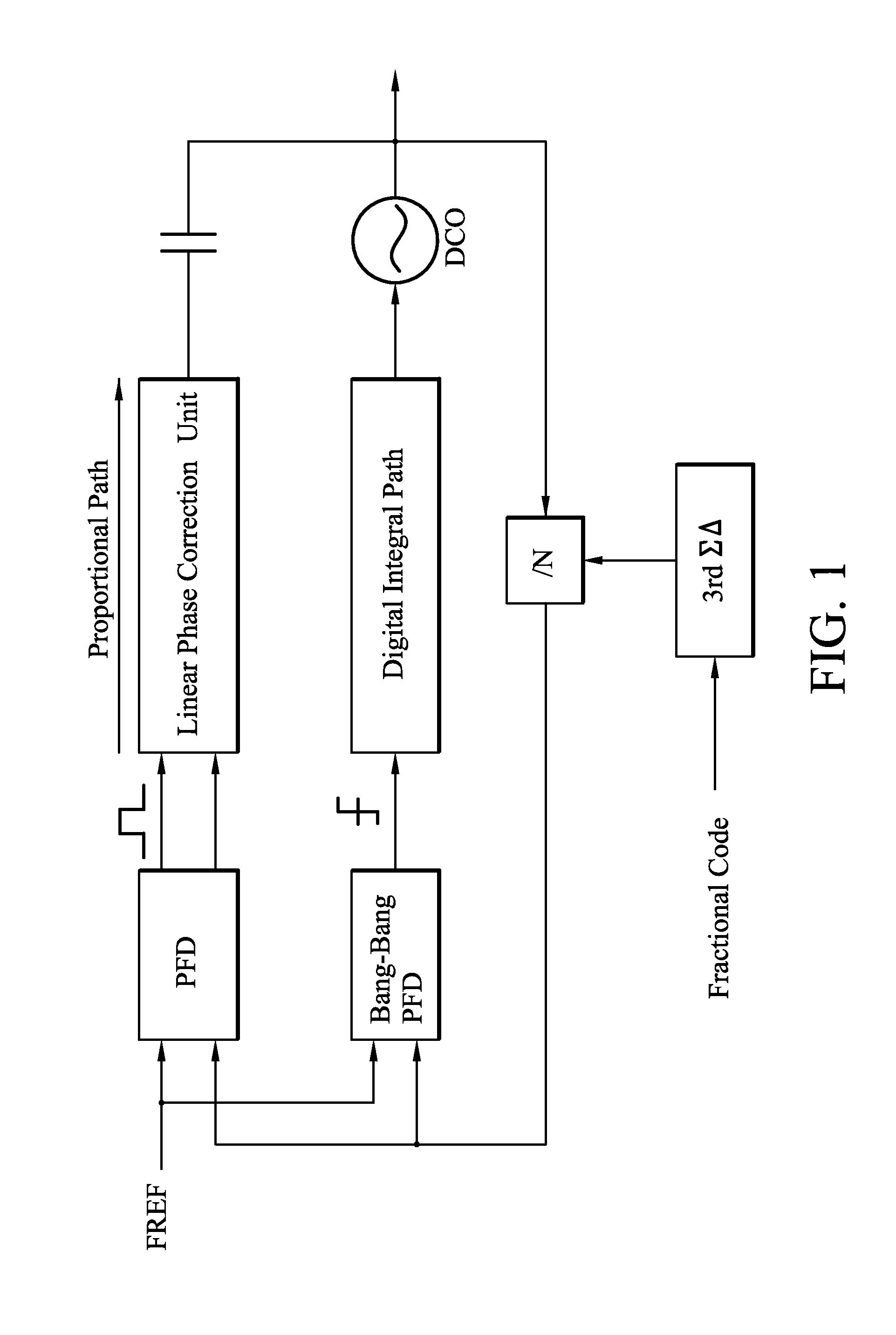
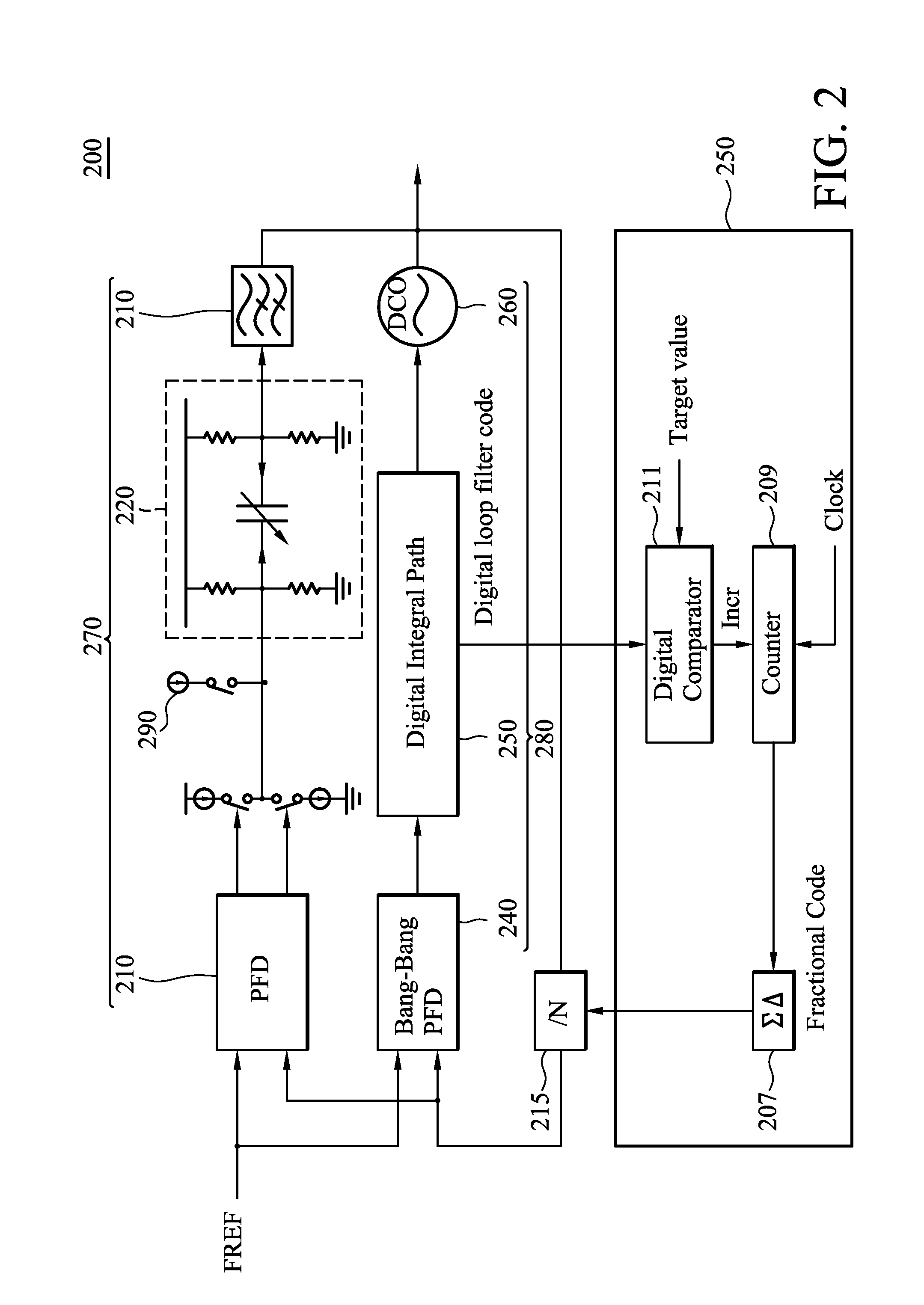
[0017]The block diagram of the DCO-based fractional-N PLL is shown in FIG. 1. The proportional path consists of a linear phase correction unit (LPCU), which is coupled with a DCO output by AC coupling capacitors. The digital integral path circuits track the frequency of the reference clock in the digital domain by a bang-bang PFD to eliminate the need for a large passive capacitor and a time to digital converter (TDC). In order to calibrate the loop bandwidth, the PLL was analyzed as follows. First, the effective capacitance of the digital filter in the integral path was realized by comparison with the linear model of the conventional digital charge pump PLL, which is:...


PUM


Abstract

A phase locked loop (PLL) with a loop bandwidth calibration circuit is provided. The mixed-mode PLL comprises an analog phase correction path, a digital frequency correction path, a calibration current source, and a loop bandwidth calibration circuit. The analog phase correction path comprises a linear phase correction unit (LPCU). The digital frequency correction path comprises a digital integral path circuit. The calibration current source is coupled to the LPCU. The loop bandwidth calibration circuit is coupled to a frequency divider and coupled between the input and output of the PLL. The loop bandwidth calibration circuit operates after the calibration current source injects a calibration current into the LPCU.

Description

BACKGROUND OF THE INVENTION[0001]1. Field of the Invention[0002]The invention relates to a phase locked loop (PLL) and, in particular, to a PLL with a calibration circuit.[0003]2. Description of the Related Art[0004]Accurate loop bandwidth calibration of a fractional-N PLL is important for ΔΣ frequency modulators because wider loop bandwidth will increase phase noise and quantization error. A lower loop bandwidth, on the other hand, will suppress modulation messages and increase phase errors.BRIEF SUMMARY OF THE INVENTION[0005]The present invention proposes a fractional-N PLL, which uses a linear PFD in a proportional path and a bang-bang PFD in an integral path. The PLL has advantages from using not only analog filters to achieve low spur and quantization error but also scalable digital filters.[0006]The proposed PLL architecture obtains accurate loop bandwidth by using a loop bandwidth calibration technique. The loop dynamic was first analyzed and then loop bandwidth circuits were...

Claims


Application Information

Patent Timeline
Patent Type & Authority Patents(United States)
IPC IPC(8): H03L7/00
CPCH03L7/087H03L7/093H03L7/1976H03L7/099
Inventor WANG, PING-YINGHSIEH, BING-YUKE, LING-WEIYU, TAI YUAN
Owner MEDIATEK INC
Why Eureka
Try Eureka