

Distribution device for fluid product
a technology for distribution devices and fluid products, applied in the direction of liquid distribution, packaging, transportation and packaging, etc., can solve the problems of high cost, complex manufacturing and assembly of aluminium reservoirs, and inability to produce complex shapes of reservoirs at reasonable costs, etc., to achieve high tensile and flexural modulus, and high shock resistance
- Summary
- Abstract
- Description
- Claims
- Application Information
AI Technical Summary
Benefits of technology
Problems solved by technology
Method used
Image

Examples
Embodiment Construction
[0005]The object of the present invention is to provide a distribution device for a fluid product which does not reproduce the aforementioned drawbacks.
[0006]More particularly, the object of the present invention is to provide such a device which guarantees the seal and the strength of the reservoir while limiting to the utmost, harmful interactions with the fluid product.
[0007]The object of the present invention is also to provide such a device with which any desired shapes may be produced for the reservoir.
[0008]The object of the present invention is also to provide such a device which is simple and not very costly to manufacture and assemble.
[0009]The object of the present invention is also to provide such a device which limits to the utmost, the use of metal, notably of aluminium.
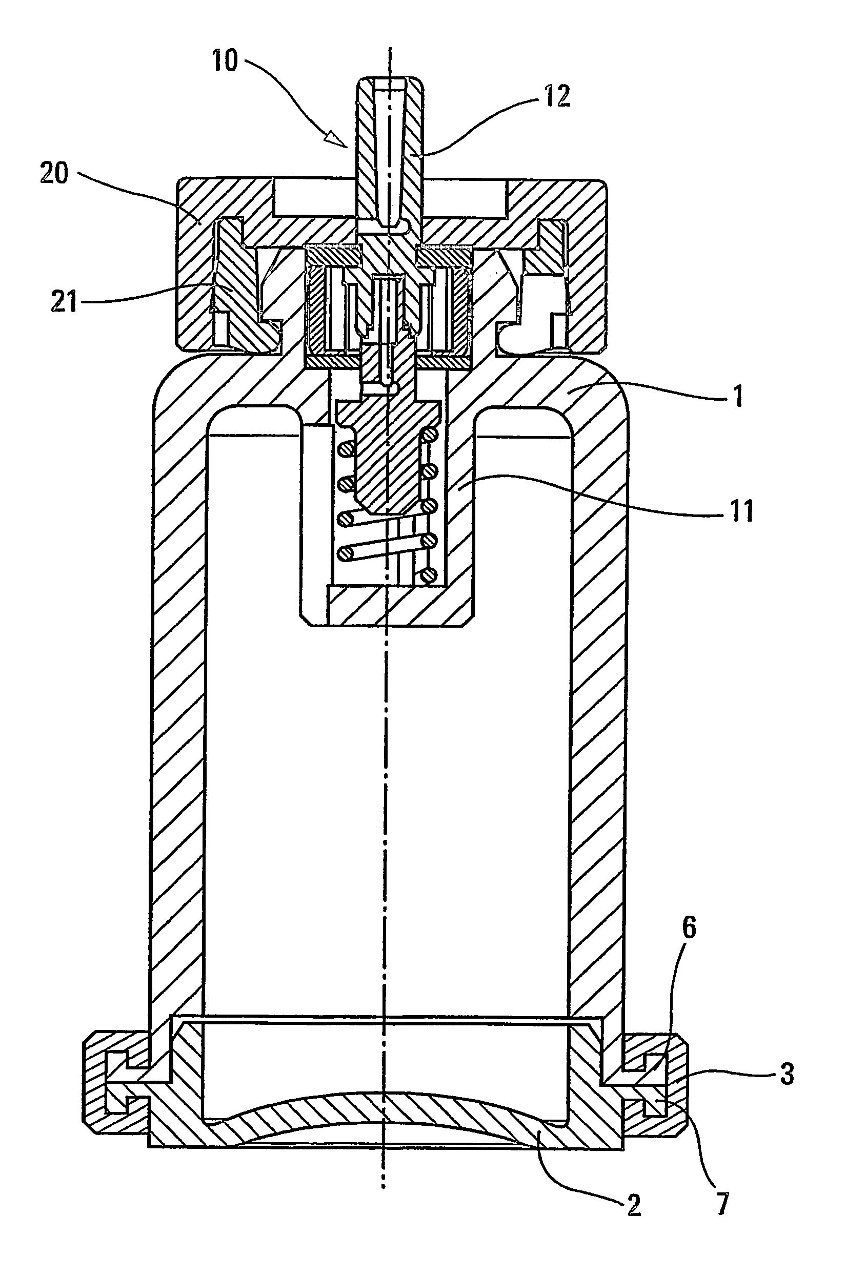
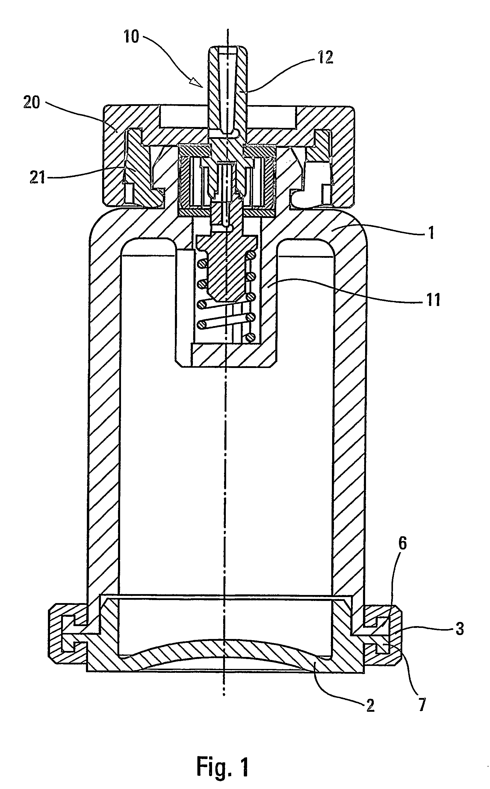
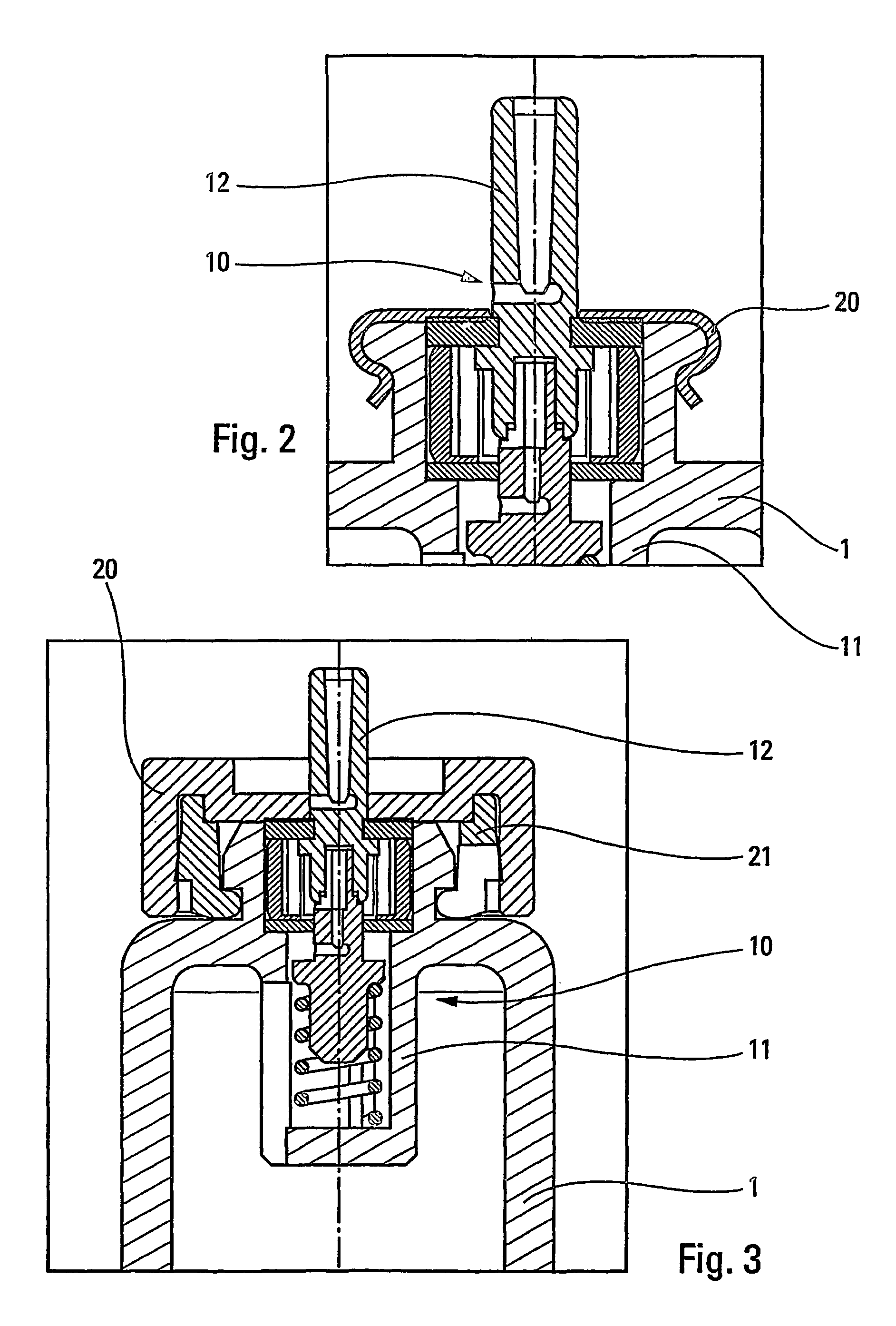
[0010]Therefore the object of the present invention is a distribution device for fluid product, including a reservoir, containing the fluid product and a propellant gas, and a valve, including a valve b...
PUM
 Abstract
Description
Claims
Application Information