Parachute release system and method

a technology of parachute and release system, applied in the field of parachutes, can solve the problems of pyrotechnic cord cutters that are typically usable, pyrotechnic cord cutters that are too large for practical handling, and the parachute system to fail

Active Publication Date: 2011-10-11
FOX JR ROY L
View PDF49 Cites 26 Cited by
  • Summary
  • Abstract
  • Description
  • Claims
  • Application Information

AI Technical Summary

Benefits of technology

The contents of this summary section are provided only as a simplified introduction to the disclosure, and are not intended to be used to limit the scope of the appended claims.

Problems solved by technology

Use of a series of parachute deployments is often necessary because the force and impulse on the suspension lines and straps of a main parachute (i.e., a parachute large enough to slow the cargo platform to an acceptable landing velocity) deploying at the terminal, free-fall velocity of the cargo platform or vehicle would be excessive, causing the parachute system to fail.
However, pyrotechnic cord cutters are typically usable only for relatively small-diameter cords.
A pyrotechnic cord cutter for payloads above a moderate size becomes too large for practical handling, and incorporates an explosive charge too large and powerful for safe handling by personnel.

Method used


Image

  • Parachute release system and method
  • Parachute release system and method
  • Parachute release system and method

Examples


Embodiment Construction

The following description is of various exemplary embodiments only, and is not intended to limit the scope, applicability or configuration of the present disclosure in any way. Rather, the following description is intended to provide a convenient illustration for implementing various embodiments including the best mode. As will become apparent, various changes may be made in the function and arrangement of the elements described in these embodiments without departing from the scope of the appended claims.

For the sake of brevity, conventional techniques for parachute construction, deployment, reefing, disreefing, release, recovery, and / or the like may not be described in detail herein. Furthermore, the connecting lines shown in various figures contained herein are intended to represent exemplary functional relationships and / or physical couplings between various elements. It should be noted that many alternative or additional functional relationships or physical connections may be pre...


PUM


Abstract

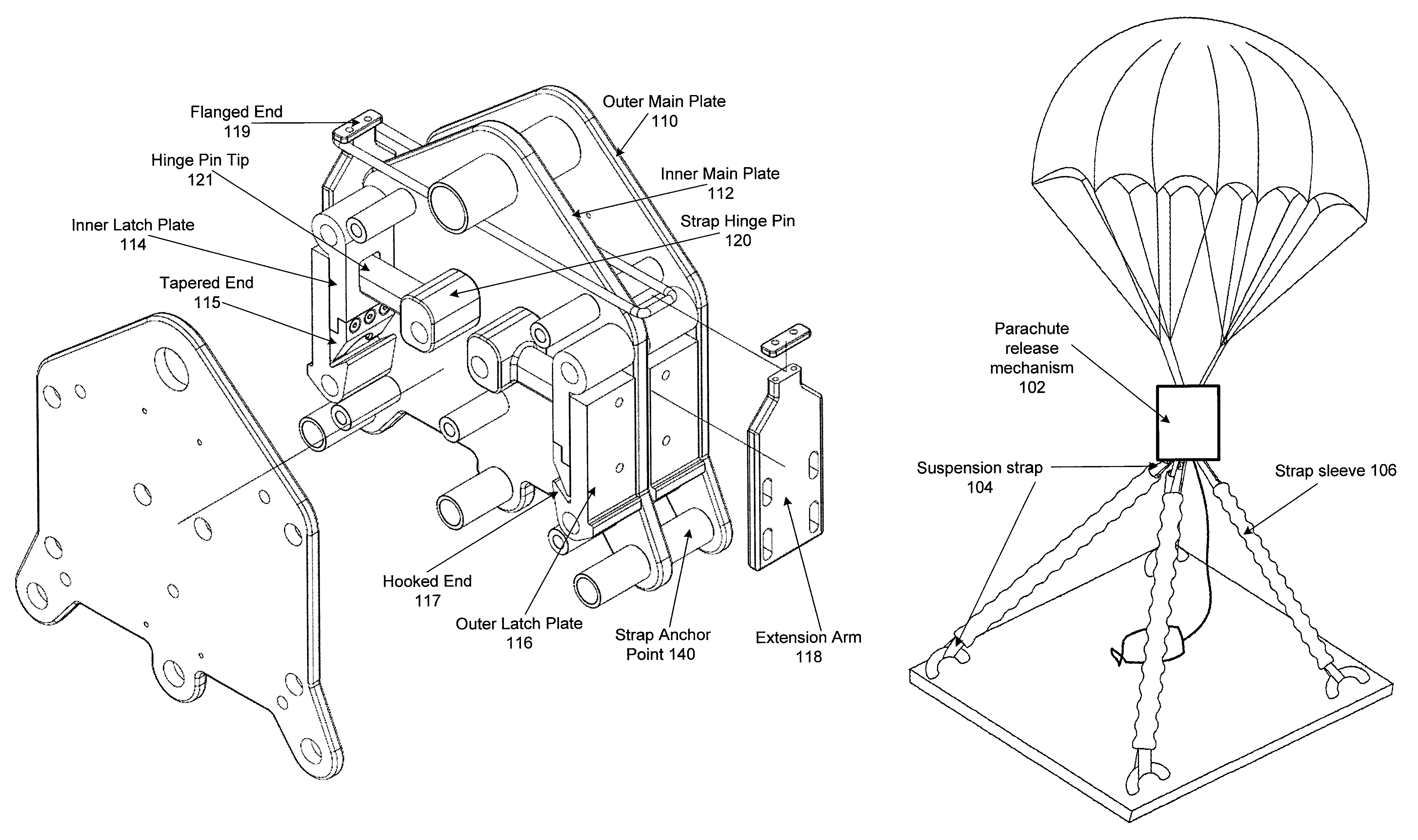
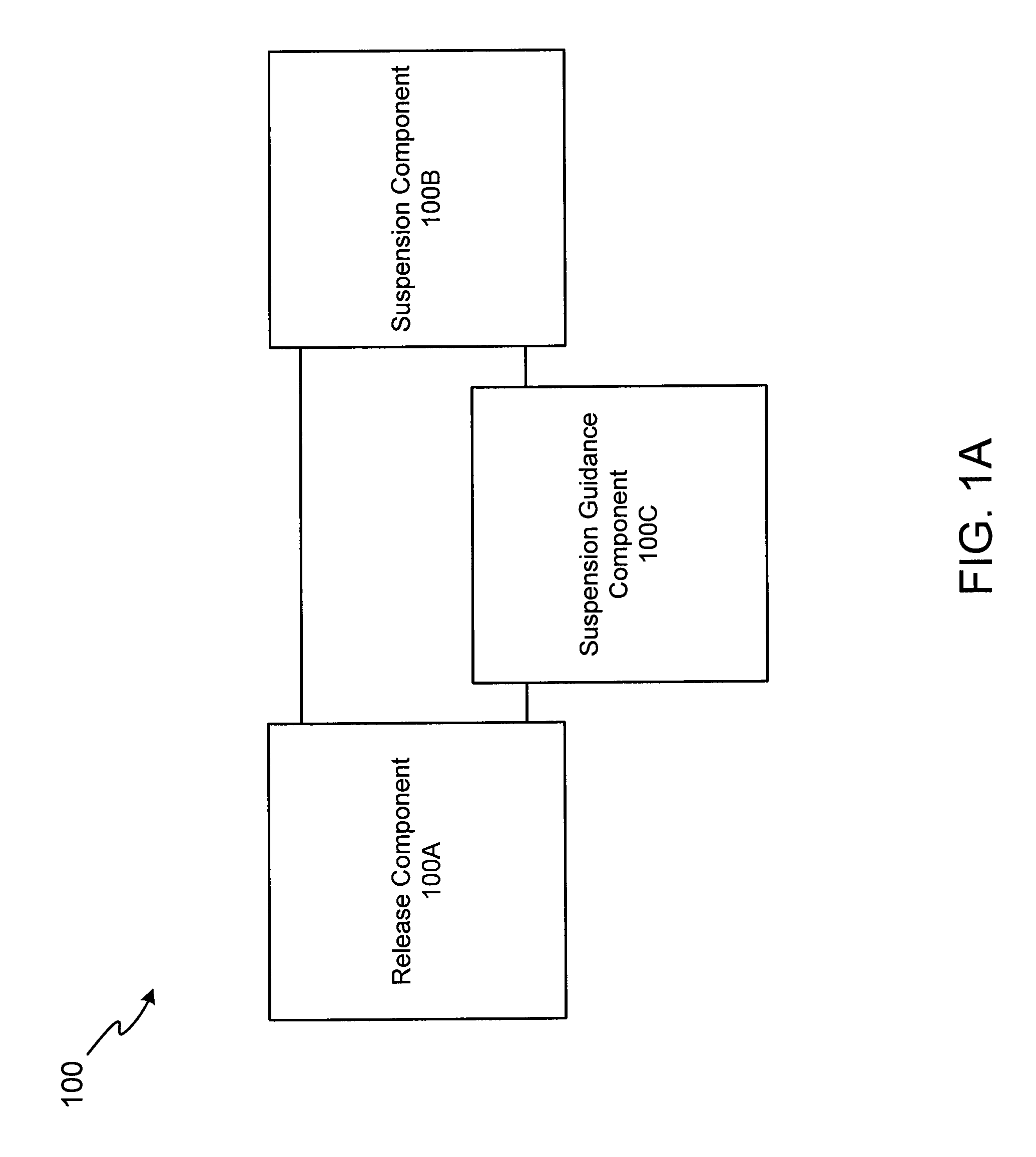
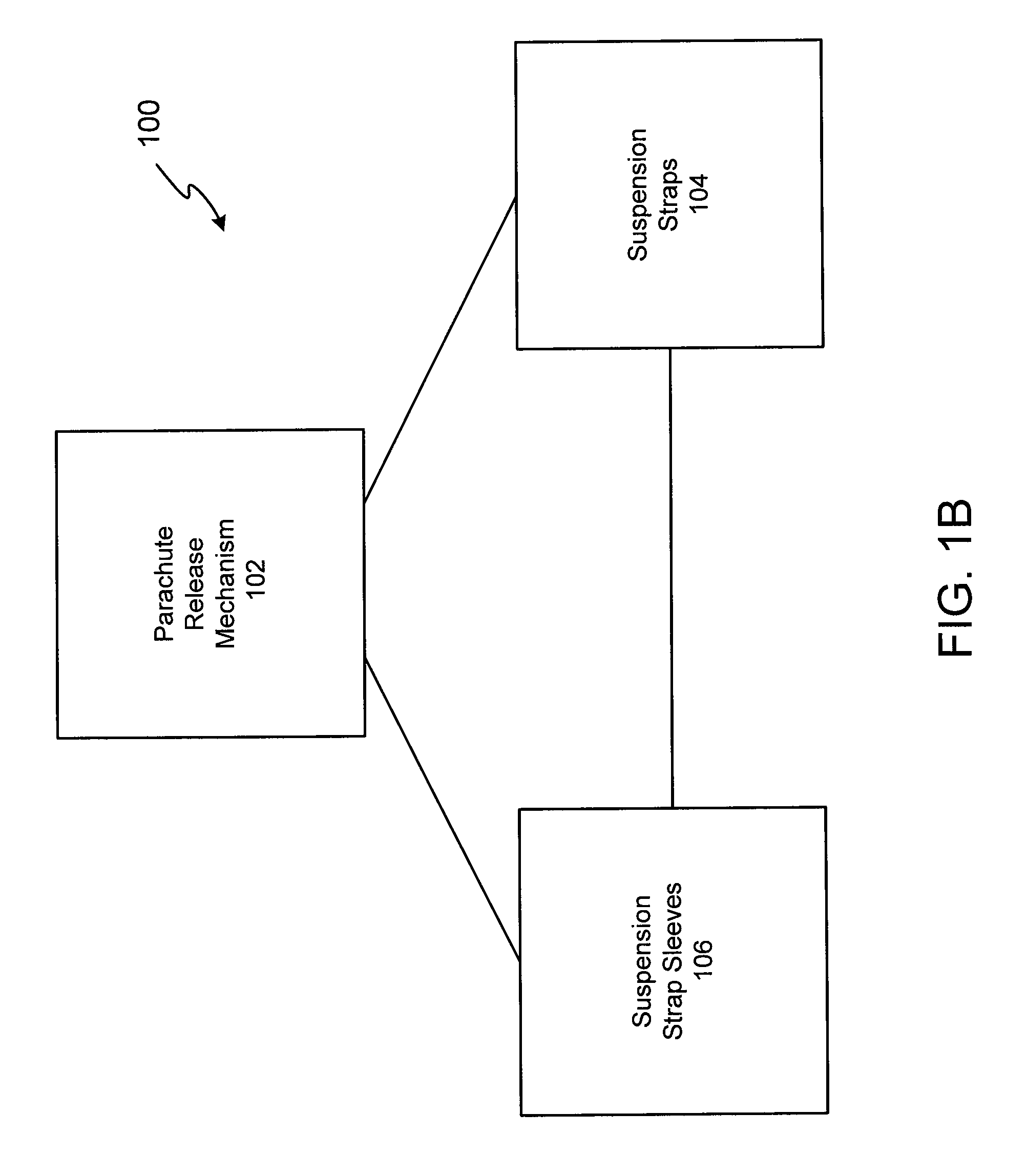
A parachute release system is configured to releasably couple a parachute to a payload. A parachute release mechanism is coupled to a suspension strap routed through a strap sleeve. The parachute release mechanism is configured to provide near-simultaneous separation of the suspension straps from the payload via operation of a rotatable hinge pin. The strap sleeve reduces the possibility of the suspension strap becoming entangled with the payload. With this system and method, larger payloads may be supported and/or the mass of the parachute release system may be reduced.

Description

TECHNICAL FIELDThe present disclosure relates to parachutes, particularly to systems and methods for releasing a deployed parachute from a suspended load in a controlled manner.BACKGROUNDAerial delivery is frequently used for transporting cargo quickly to areas of limited or hostile access, for example areas without the availability of nearby airports. At times, people in isolated areas, such as jungles, deserts, mountains, polar regions, combat zones, and the like are in need of essential supplies, including food and medical supplies, but are not within access to an airport at which a supply plane could land. In these instances, aerial delivery of cargo from in-flight aircraft may be the sole option. Aerial delivery systems involve the use of parachute systems to slow the descent and gently land the cargo platforms on the ground.Similar parachute systems are utilized for recovery of aeronautical and astronautical vehicles, including rocket boosters, experimental aircraft and space ...

Claims


Application Information

Patent Timeline
Patent Type & Authority Patents(United States)
IPC IPC(8): B64D17/38
CPCB64D17/383
Inventor FOX, JR., ROY L
Owner FOX JR ROY L
Why Eureka
Try Eureka