Crossed gap ferrite cores

a cross-gap, ferrite core technology, applied in the field of inductors, can solve the problems of reducing the cross-sectional area of the core available for energy storage, increasing the ripple on the output, and large physical inductance overspecified,

Inactive Publication Date: 2011-10-11
POWER INTEGRATIONS INC
View PDF25 Cites 6 Cited by
  • Summary
  • Abstract
  • Description
  • Claims
  • Application Information

AI Technical Summary

Benefits of technology

[0014]By providing such a cross arrangement, the inductor is less susceptible to the influence of misalignment errors resulting from core and bobbin tolerances, thereby enabling more reproducible inductance performance. Broadly speaking, this is because a substantially constant area of crossover between opposed ridges can be maintained. Appropriate dimensioning and positioning of the ridges on the distal ends facilitates variable sizing of this area.
[0015]In some preferred embodiments, the role of physically bridging a gap between two core segments is shared equally between opposingly paired projecting ridges. This is advantageous since the resulting ridges may be reduced in height compared to the situation where only one ridge is provided for a pair of opposed distal ends. Thus, increased robustness and ease of manufacture may be achieved since ridges of core segments become less susceptible to damage.
[0017]In some preferred embodiments the first and second core segments are substantially identical. This significantly reduces the likelihood of incorrectly mixing core segments, and makes assembly of the inductor easier. However, in other preferred embodiments, asymmetrical cores may be implemented. For example, one core could have a relatively larger ridge compared to the opposing ridge.
[0024]This is advantageous as the core segments could be manufactured without the need for post-processing, such as grinding, to refine the gap. The material could be a single homogeneous mass of ferrite material.

Problems solved by technology

For such applications, swinging inductors offer a good practical compromise between designing for maximal load, in which case the inductance may be too low to meet the ‘critical’ inductance required at light load (i.e. that inductance necessary to prevent the inductor current from going to zero) and which may result in increased ripple on the output, and designing for increased inductance, which may result in a physically large inductor that is overspecified for the nominal load of the application.
However, larger ungapped sections reduce the cross-sectional area of the core available for energy storage at higher DC bias, i.e. gapped sections 208.
However, narrower ungapped sections are prone to misalignment when the cores are assembled onto a bobbin, with resulting inconsistencies in manufacture.
The problem is exacerbated with smaller cores, largely due to tolerances of core and bobbin dimensions, where a bobbin might accept a range of core halves varying in size by around ±10%.
Those core halves at the smaller end of this range may not securely engage together and could therefore slip out of position.
Since the core's low load inductance properties depend on the contact area (or relative closeness, as the case may be for a fully gapped structure) of the step gap, such 10% linear variations may become detrimental.
Existing core configurations and manufacturing techniques are not entirely satisfactory at mitigating the detrimental effects of misalignment and ensuring a consistent inductor characteristic, and there is therefore a need for improved techniques.

Method used


Image

  • Crossed gap ferrite cores
  • Crossed gap ferrite cores
  • Crossed gap ferrite cores

Examples


Embodiment Construction

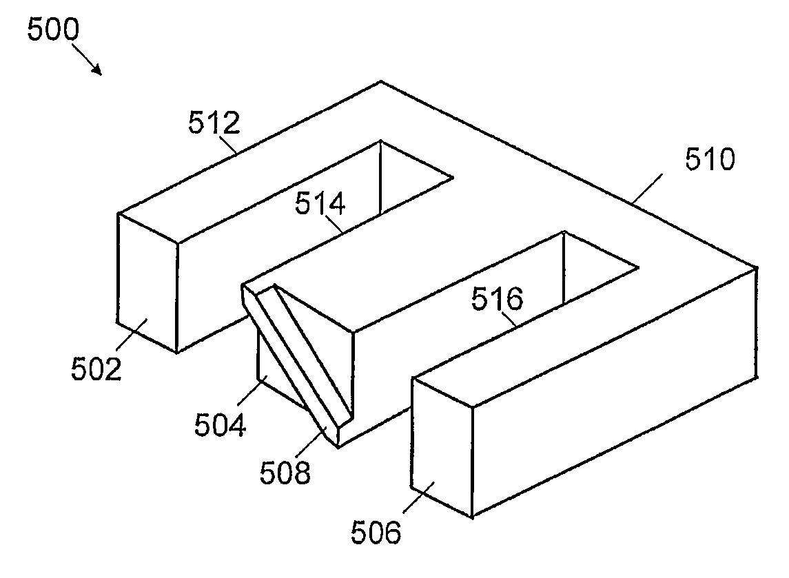
[0033]In one specific embodiment of the present invention shown in FIG. 5, an E-shaped core segment 500 has a base 510 from which a plurality (in this case three) of legs 512, 514, 516 extend in a direction perpendicular thereto. The legs are spaced apart to allow a coil (not shown) to be fit over the top of, for example, the central leg. Each of the legs has a respective end surface 502, 504, 506. The central leg 504 has a protruding ridge 508 running diagonally across the rectangular surface from one corner to another. In this particular embodiment, end surfaces 502, 506 are flat and co-planar with the plateau of ridge 508.

[0034]In FIG. 6, the core segment 500 is shown as seen when viewed looking at the end surfaces 502, 504, 506. Like reference numbers are used to denote like parts.

[0035]An advantage of such an arrangement is that the likelihood of incorrectly mixing cores is essentially prevented, since two of the same core segments can be mated in only one possible orientation ...


PUM

PropertyMeasurementUnit
angleaaaaaaaaaa
inductanceaaaaaaaaaa
currentaaaaaaaaaa

Abstract

The invention relates to swinging inductors of a stepped-gap construction. We describe an inductor core structure having first and second core segments, constructed and arranged such that distal ends of legs of the first core segment are paired with distal ends of legs of the second core segment in an opposing relation. The at least one distal ends of the first core segment has a ridge projecting therefrom and is paired with the at least one distal ends of the second core segment which has a ridge projecting therefrom in an opposing relation, such that opposingly paired projecting ridges form a cross arrangement.

Description

RELATED APPLICATION[0001]This application priority under 35 U.S.C. 119 to United Kingdom Patent Application Serial No. 0816921.1, filed Sep. 16, 2008; which application is incorporated herein by reference and made a part hereof.FIELD OF THE INVENTION[0002]The invention relates generally to the field of inductors, and more particularly to swinging inductors of a stepped-gap construction.BACKGROUND TO THE INVENTION[0003]Swinging inductors, often also referred to as swinging chokes, exhibit a relatively large inductance at light load and a progressively smaller inductance as the load increases. This makes them well suited for applications requiring good output regulation in the presence of variable load conditions. Switching power supplies and electronic ballasts are typical examples.[0004]For such applications, swinging inductors offer a good practical compromise between designing for maximal load, in which case the inductance may be too low to meet the ‘critical’ inductance required ...

Claims


Application Information

Patent Timeline
Patent Type & Authority Patents(United States)
IPC IPC(8): H01F27/24
CPCH01F3/14H01F41/0246H01F37/00H01F27/263Y10T29/49075H01F27/26
Inventor VAIL, DAVID
Owner POWER INTEGRATIONS INC
Why Eureka
Try Eureka