
Semi-conductive ceramic material and NTC thermistor using the same

a technology of semi-conductive ceramics and thermistors, which is applied in the direction of resistors, thermistors, basic electric elements, etc., can solve the problems of high cost and difficulty in selecting materials which make linearized resistance-temperature characteristics, and achieve linearized resistance-temperature characteristics and linearized resistance-temperature characteristics.

Inactive Publication Date: 2011-10-11
MURATA MFG CO LTD
View PDF16 Cites 2 Cited by
  • Summary
  • Abstract
  • Description
  • Claims
  • Application Information

AI Technical Summary

Benefits of technology

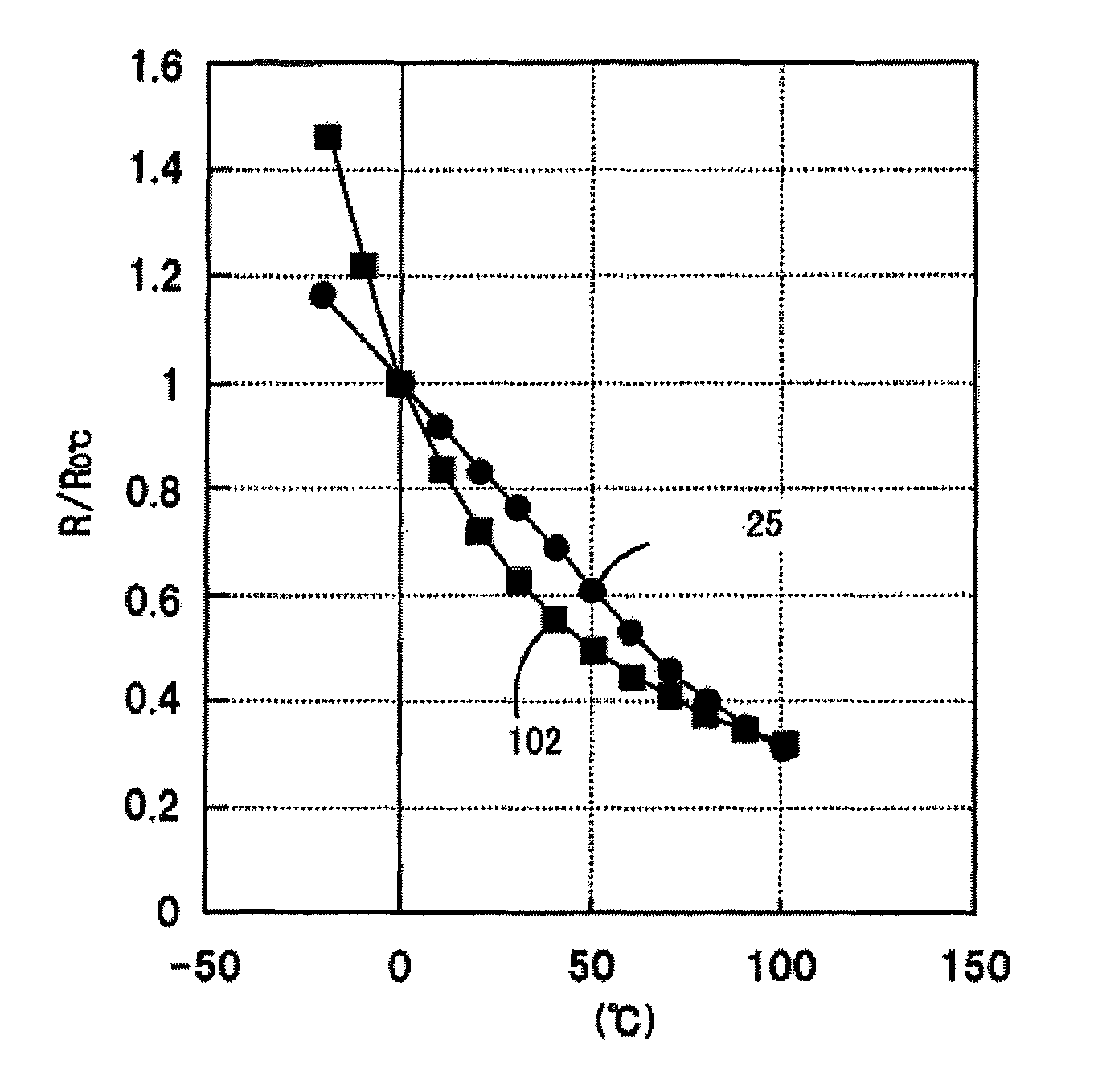
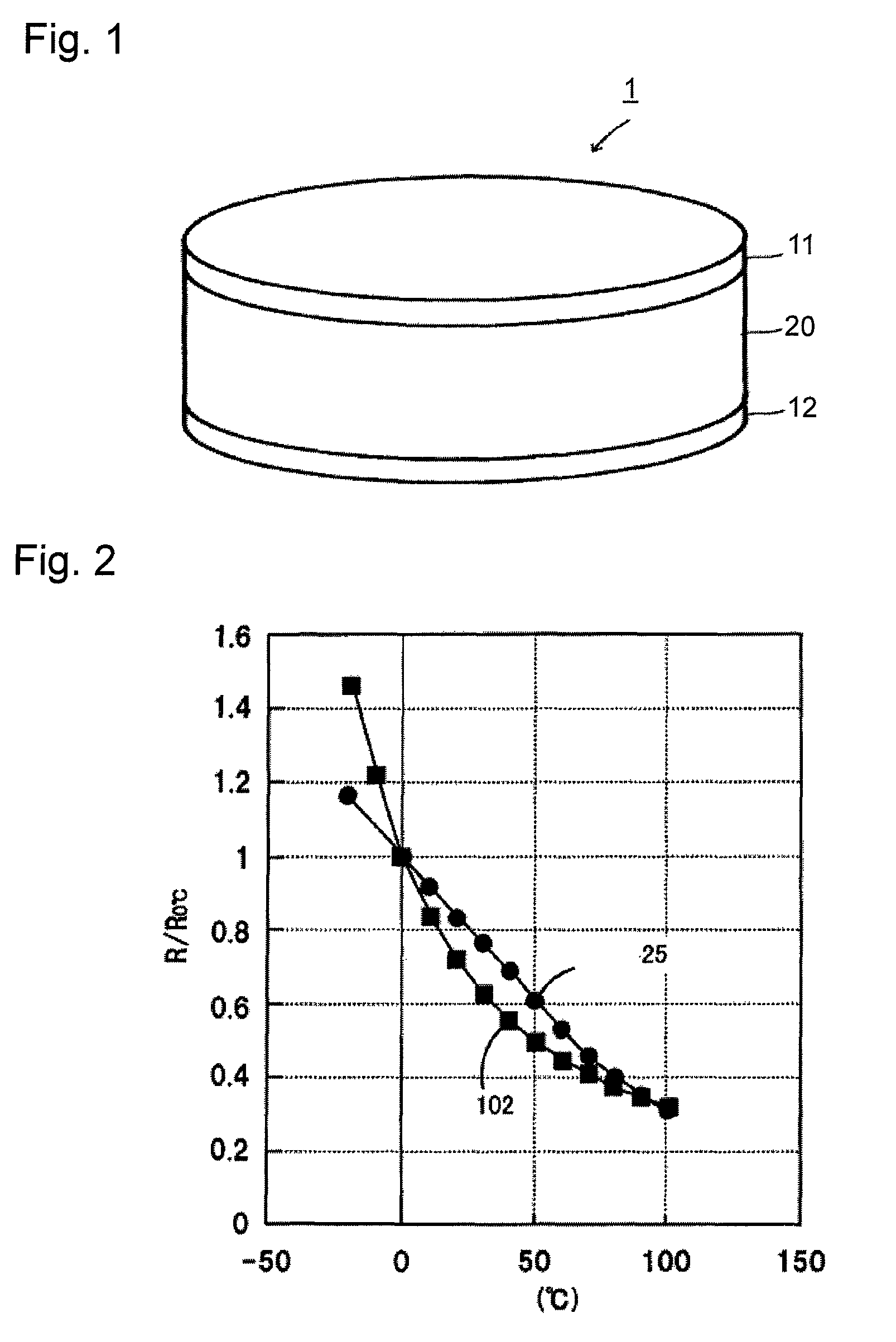
[0016]With a semi-conductive ceramic material according to the present invention, a linearized negative resistance-temperature characteristic is achieved by itself. Accordingly, a NTC thermistor having linearized resistance-temperature characteristic can be provided easily.
[0013]As a semi-conductive ceramic material of this invention, preferably when x=1 and y=0.8 to 1.5, the content of the barium element in A is 69 to 72 mol %, and when x=1 and y=2.0 to 2.1, the content of the barium element in A is 54 to 63%.
[0018]Since the NTC thermistor according to the present invention is composed of a single semi-conductive ceramic material, unlike being composed with two or more kinds of ceramic layers, characteristic change during firing, cracks due to a difference of the linear coefficients of expansion, and so forth can be avoided. In addition, since the NTC thermistor according to the present invention has a linearized resistance-temperature characteristic by itself, adjusting resistance-temperature characteristic by providing an IC device or a resistor in a circuit is not required.

Problems solved by technology

However, that method requires a complicated circuit and results in higher cost.
According to the method disclosed in the Patent Documents 1 to 3, problems exists in that at least two kinds of thermistor material must be prepared and, furthermore, selecting material which make a linearized resistance-temperature characteristic is difficult.

Method used


Image

  • Semi-conductive ceramic material and NTC thermistor using the same
  • Semi-conductive ceramic material and NTC thermistor using the same
  • Semi-conductive ceramic material and NTC thermistor using the same

Examples


Embodiment Construction

[0024]FIG. 1 is a perspective view illustrating an NTC thermistor 1 in accordance with an embodiment of the present invention.

[0025]The NTC thermistor includes electrodes 11 and 12 and a ceramic body 20 sandwiched between the electrodes 11 and 12. The electrodes 11 and 12 can be composed of Ag, Ag—Pd, Pd, Pt, or Au, or alloy including these metals. The ceramic body is composed of a semi-conductive ceramic material in accordance with the present invention.

[0026]Although FIG. 1 shows a disc shape NTC thermistor 1, a rectangular block shape may be used. A multilayer configuration with internal electrodes may be used as well.

[0027]The semi-conductive ceramic material which constitutes the ceramic body has a negative resistance-temperature characteristic and is composed of an oxide which is expressed by general formula AxByOz (where z is determined by valencies of the elements of A and B and amounts of x and y, and keeps electric neutrality of the ceramic), wherein A includes a rare eart...


PUM

PropertyMeasurementUnit
thicknessaaaaaaaaaa
sizeaaaaaaaaaa
resistance-temperatureaaaaaaaaaa

Abstract

A NTC thermistor which has superior linearity of resistance-temperature characteristic is provided without depending on a combination of two or more kinds of material but with a single semi-conductive ceramic material. As the semi-conductive ceramic material of negative resistance-temperature characteristic is a ceramic body constituting a NTC thermistor being an oxide expressed by the formula AMnyOz in which y is 0.8 to 1.6, A is a combination of rare earth element and barium and the content of barium in A is 60 to 75 mol % when y=0.8 to 1.5, and 50 to 63 mol % y=1.7 to 2.3, and z is a value which maintains the electric neutrality of the oxide. A preferable oxide is of the formula (La1-αBaα)MnyOz in which when y=0.8 to 1.5, 0.60≦α≦0.75, and when y=1.7 to 2.3, 0.50≦α≦0.63.

Description

[0001]This is a continuation of application Ser. No. PCT / JP2008 / 064093, file Aug. 6, 2008, which is hereby incorporated herein by reference.TECHNICAL FIELD[0002]The present invention relates to a semi-conductive ceramic material having a negative resistance-temperature characteristic and an NTC thermistor produced with the material, providing a technology improving the linearity of resistance-temperature characteristic of the thermistor.BACKGROUND ART[0003]NTC thermistors are thermistors which have a negative resistance-temperature coefficient, that is, NTC thermistors have relatively high resistance at room temperature which decreases as the temperature is increased. Therefore, NTC thermistors are used as a temperature sensor or in a temperature compensation circuit, for example.[0004]Generally, the resistance-temperature characteristic of an NTC thermistor is not linear. When an NTC thermistor is utilized as the above described temperature sensor or in a temperature compensation c...

Claims


Application Information

Patent Timeline
Patent Type & Authority Patents(United States)
IPC IPC(8): H01C7/10
CPCC04B35/016C04B35/63488H01C7/008H01C7/043H01C17/06533C04B2235/3215C04B2235/3227C04B2235/3263C04B2235/6025C04B2235/79
Inventor MIURA, TADAMASA
Owner MURATA MFG CO LTD
Learn More