Solenoid valve having a hollow cap mounted on a leading end of a movable iron core

a technology of solenoid valve and hollow cap, which is applied in the direction of valve housing, valve operating means/release devices, machines/engines, etc., can solve the problems of easy wear of valve members, valve members hitting the valve seat, and movable iron core detachment, so as to reduce wear and increase the durability of valve members , the effect of high impa

Active Publication Date: 2011-10-18
SMC CORP
View PDF10 Cites 7 Cited by
  • Summary
  • Abstract
  • Description
  • Claims
  • Application Information

AI Technical Summary

Benefits of technology

[0006]It is therefore an object of the present invention to address the above-described known problems of a solenoid valve and reduce wear of a valve member and a transmission member to increase durability as well as responsivity.
[0015]As a result, since an inertial force of the movable iron core is absorbed by compressing the cushioning spring, the valve member does not hit the valve seat hard and the pressing member does not abut on the transmission member with high impact, resulting in reduced wear and increased durability of the valve member and the transmission member.
[0016]Also, when the movable iron core assembly is shifted from the initial position to the working position by energizing the exciting coil, the cushioning spring being compressed presses the movable iron core toward the fixed iron core to assist an attracting behavior, resulting in quick and easy initial movement of the movable iron core as well as improved responsiveness.

Problems solved by technology

However, if the solenoid valve is switched from a valve-opening state in which the exciting coil is energized and the iron core return spring is compressed by the movable iron core to the valve-closing state by turning off the energization to the exciting coil, the movable iron core detaches from the fixed iron core at high velocity, causing the valve member to hit the valve seat with high impact by a inertial force of the movable iron core.
Thus, there is a problem that the valve member is easily worn away.
Also, there is another problem that a transmission member (a pushrod) provided between the movable iron core and the valve member to transmit an acting force of the movable iron core to the valve member is easily worn away.

Method used


Image

  • Solenoid valve having a hollow cap mounted on a leading end of a movable iron core
  • Solenoid valve having a hollow cap mounted on a leading end of a movable iron core
  • Solenoid valve having a hollow cap mounted on a leading end of a movable iron core

Examples


Embodiment Construction

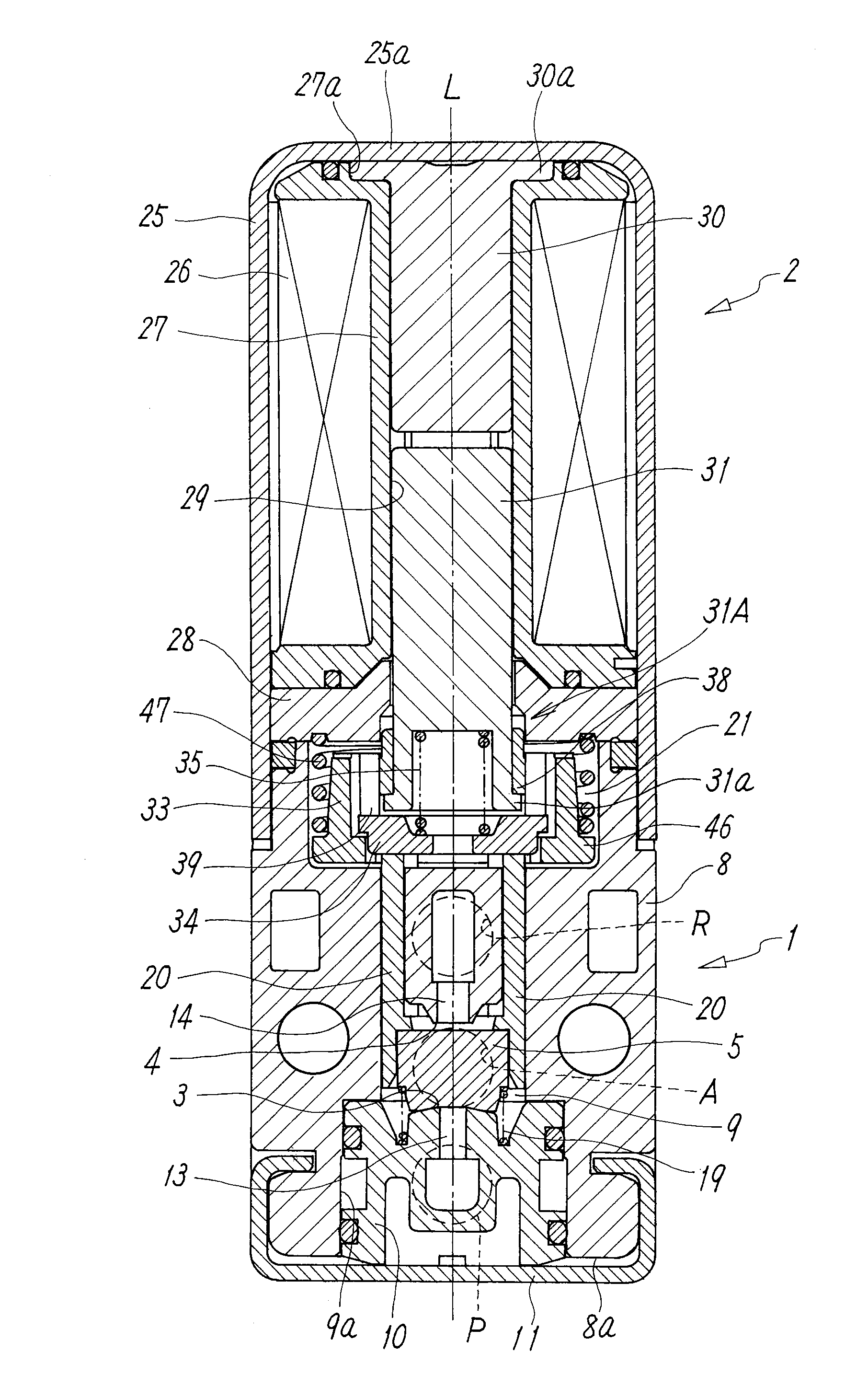
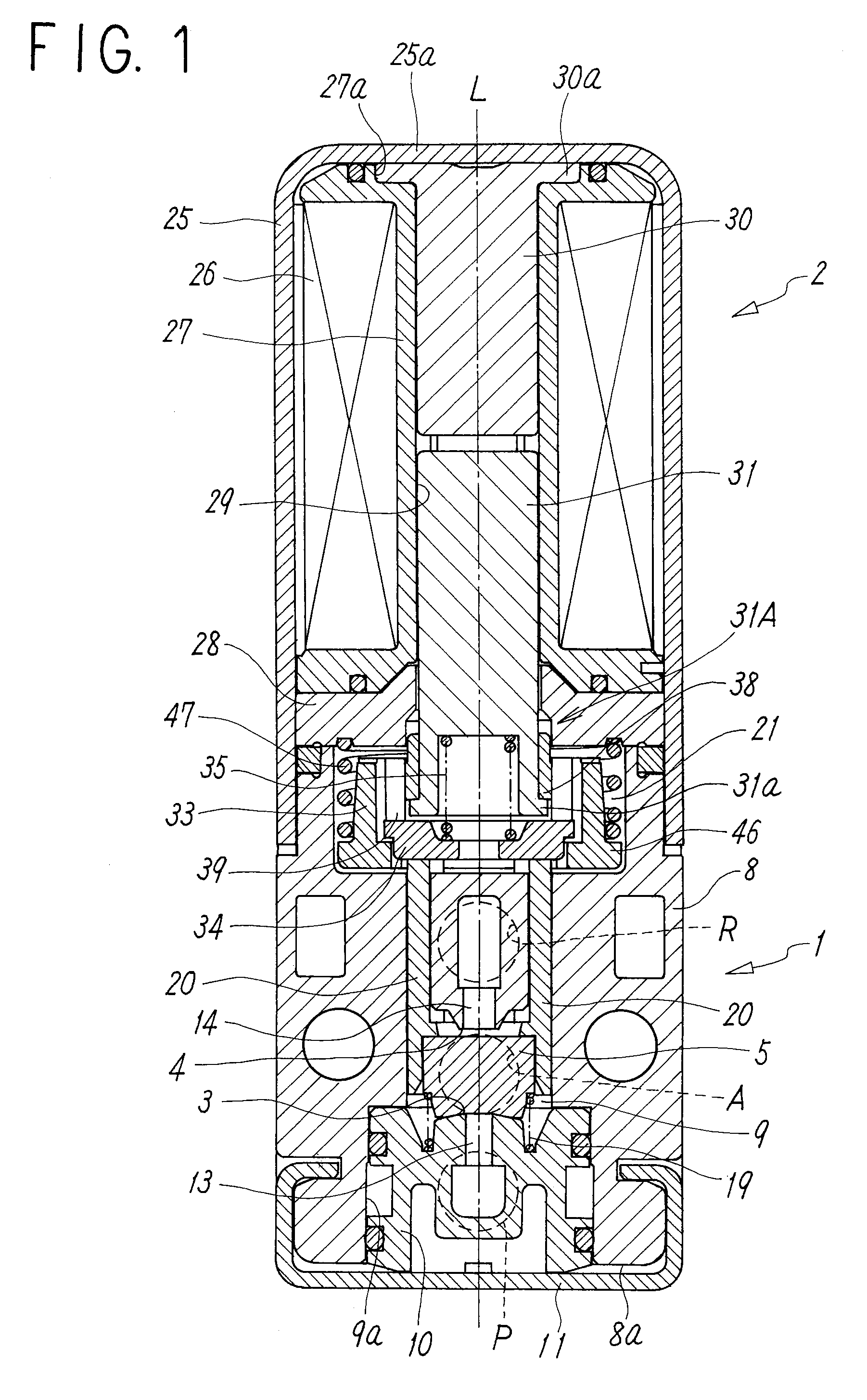
[0021]In FIG. 1, a three-port solenoid valve is shown as an exemplary embodiment of the solenoid valve according to the present invention. This solenoid valve comprises a main valve portion 1 having a poppet-type valve member 5 that detaches from and attaches to two valve seats 3 and 4 to open and close a flow path, and a solenoid operation portion 2 for operating the valve member 5, the main valve portion 1 and the solenoid operation portion 2 being associated in tandem along a valve axis L that is a central axis of the solenoid valve.

[0022]The main valve portion 1 has a valve body 8 made of a substantially square block, the block having a supply port P, an output port A, and an exhaust port R formed on one side surface thereof. In the valve body 8, a circular bore 9a that forms a valve chamber 9 is provided so as to extend from an end surface 8a, opposite the end surface with which the solenoid operating portion 2 is associated, into the interior of the valve body 8. A circular va...


PUM


Abstract

A solenoid valve that is constructed as follows: a cap is mounted on a movable iron core such that forward movement thereof is restricted; a pressing member is displaceably arranged between abutting seat surfaces of the cap and the movable iron core; biasing forces F1, F2, and F3 of an iron core return spring for biasing the movable iron core toward a initial position, a cushioning spring provided between the movable iron core and the pressing member, and a valve return spring for biasing a valve member in a direction to open a valve are set so as to be F1>F2>F3; and gaps x and y are provided between the pressing member and the movable iron core and between the pressing member and the cap, respectively, when the movable iron core is at the initial position.

Description

TECHNICAL FIELD[0001]The present invention relates to a solenoid valve of a type that opens and closes a valve member in a direct-acting manner by using a movable iron core of a solenoid operation portion.BACKGROUND ART[0002]A solenoid valve of a type that opens and closes a valve member in a direct-acting manner by using a movable iron core of a solenoid operation portion is known, as is disclosed, for example, in Japanese Unexamined Patent Application Publication No. 2004-156709.[0003]A solenoid valve of this type generally comprises a fixed iron core and a movable iron core that adhere to each other by a magnetic force generated by energizing an exciting coil, a poppet-type valve member that attaches to and detaches from a valve seat by an action of the movable iron core to close and open a flow path, an iron core return spring that biases the movable iron core toward an initial position (a valve-closing position at which the valve member abuts on the valve seat) at which the mov...

Claims


Application Information

Patent Timeline
Patent Type & Authority Patents(United States)
IPC IPC(8): F16K31/02
CPCF16K31/0627Y10T137/86686Y10T137/86622F16K1/36F16K1/42F16K27/029H01F7/16
Inventor MATSUMOTO, TAKUMINARITA, MASARU
Owner SMC CORP
Why Eureka
Try Eureka