Method for measuring an ionization current of a spark plug of the type with resonant structure and corresponding device

a technology of ionization current and spark plug, which is applied in the direction of engine ignition, machine/engine, ignition control, etc., can solve the problems of fuel being jammed against the walls, reaching the self-ignition point and then igniting point, and destroying the piston and the walls of the cylinder

Inactive Publication Date: 2011-10-18
RENAULT SA
View PDF6 Cites 4 Cited by
  • Summary
  • Abstract
  • Description
  • Claims
  • Application Information

AI Technical Summary

Benefits of technology

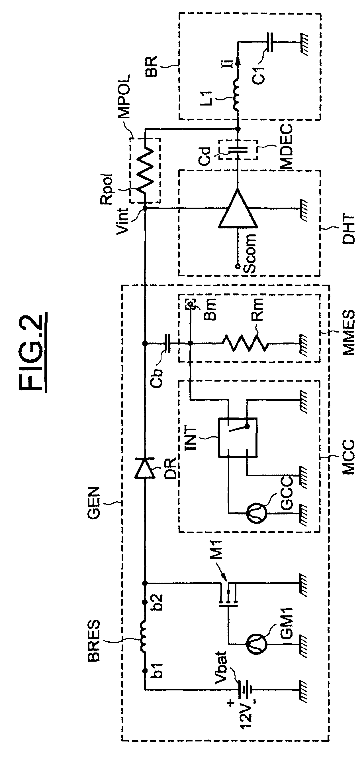
[0029]FIG. 2 more accurately illustrates an embodiment of the invention;
[0030

Problems solved by technology

The rise in pressure and temperature is so great that the fuel can remain jammed against the walls, reach its self-ignition point and then ignite in several places.
These vibrations are very strong and can rapidly create hot spots which further accentuate

Method used


Image

  • Method for measuring an ionization current of a spark plug of the type with resonant structure and corresponding device
  • Method for measuring an ionization current of a spark plug of the type with resonant structure and corresponding device
  • Method for measuring an ionization current of a spark plug of the type with resonant structure and corresponding device

Examples


Embodiment Construction

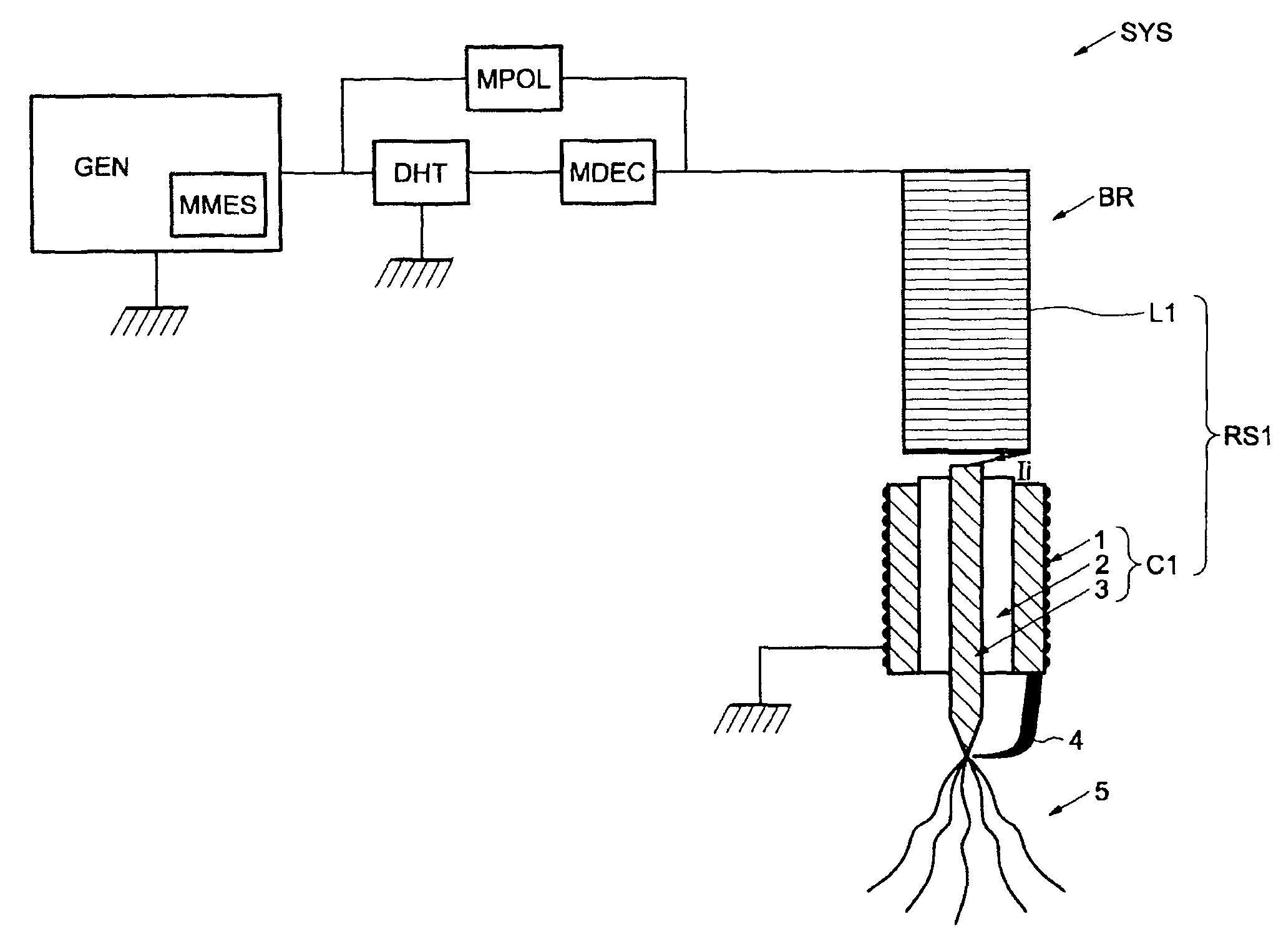
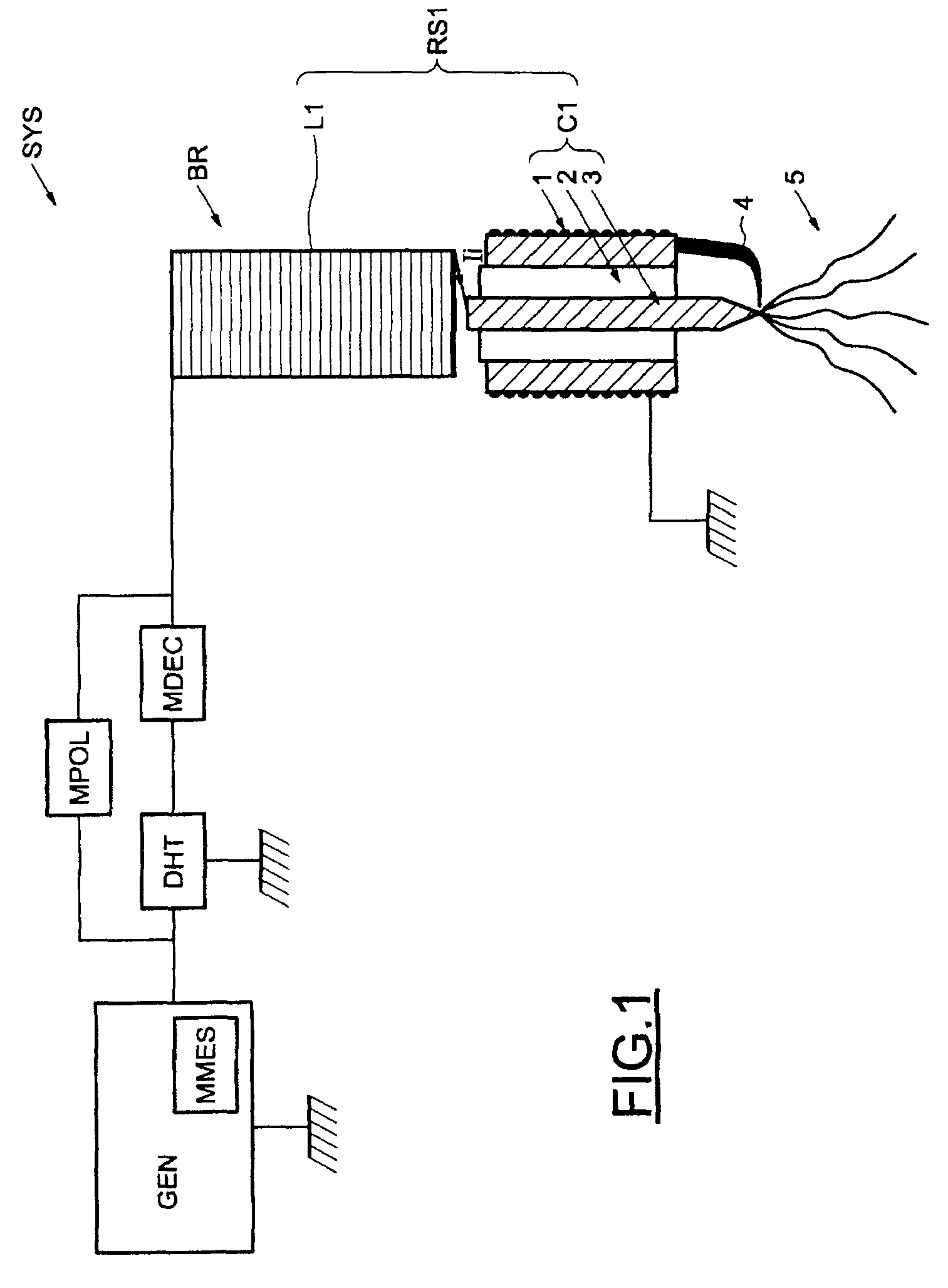
[0033]In FIG. 1, the reference SYS represents an ignition system for motor vehicles comprising a spark plug BR of resonant structure type, well known to those skilled in the art, and described, for example, in the French patent applications FR 2 859 830, FR 2 589 869 and FR 2 859 831, in the name of the Applicant.

[0034]An ionization current Ii circulates through the spark plug BR.

[0035]More specifically, as illustrated diagrammatically in FIG. 1, the spark plug BR comprises a resonant assembly RS1 (called spark plug coil), comprising an inductive coil L1 and a capacitor C1 which in this example comprises a shell 1-ceramic 2-central electrode 3 assembly.

[0036]The spark plug BR is connected to a generator GEN able to generate a high-value voltage called “intermediate voltage”. This high voltage is directed by the central electrode 3 of the capacitor C1. An electric arc is produced when the current passes between the central electrode 3 and a ground electrode 4, generating a spark 5.

[0...


PUM


Abstract

A device for measuring an ionization current of a spark plug of a type with a resonant structure, including a motor vehicle ignition system, the spark plug being coupled to a generator including a regulating capacitor. The generator includes a polarizer that polarizes the spark plug, connected between the generator and the spark plug, and a device that measures ionization current of the spark plug, connected between the regulating capacitor and ground.

Description

BACKGROUND OF THE INVENTION[0001]The present invention relates, generally, to the measurement of an ionization current of a spark plug, in particular of resonant structure type spark plugs, used in ignition systems for motor vehicles.[0002]The invention is particularly suitable for so-called “radiofrequency” ignition systems comprising multiple-spark type resonant structure spark plugs or BME.[0003]These ignition systems using alternating currents are described, for example, in the French patent applications FR 2 859 830, FR 2 589 869 and FR 2 859 831, in the name of the Applicant.[0004]At the end of the compression cycle, the spark plug is responsible for forming an electrical arc, the energy of which is sufficient to trigger the process of ignition of the gaseous mixture contained in the combustion chamber of the engine.[0005]This electrical arc corresponds to the ionization of the gaseous mixture located between the electrodes of the spark plug, respectively a positive central el...

Claims


Application Information

Patent Timeline
IPC IPC(8): F02P17/00
CPCF02P3/01F02P9/007F02P15/08F02P17/12F02P2017/125
Inventor AGNERAY, ANDRENOUVEL, CLEMENT
Owner RENAULT SA
Why Eureka
Try Eureka