Throwing wheel assembly

Active Publication Date: 2011-10-25
BLAST CLEANING TECH INC
View PDF14 Cites 6 Cited by
  • Summary
  • Abstract
  • Description
  • Claims
  • Application Information

AI Technical Summary

Benefits of technology

[0010]The present invention satisfies the need and alleviates the problems discussed above. In one aspect, there is provided an improved throwing apparatus of the type comprising a rotatable wheel and a plurality of throwing blades positionable on a forward face thereof, the rotatable wheel having an axis of rotation and each of the throwing blades having a holding structure projecting therefrom. The improvement comprises: (a) the forward face of the rotatable wheel including a recess surrounded by a forward peripheral portion of the forward face such that at least a portion of the recess is bounded circumferentially by an axially extending interior wall of the forward peripheral portion; (b) a blade retainer groove provided in the recess of the forward face proximate a rearward end of the interior wall for removably receiving a blade retainer; (c) a plurality of slots extending through the interior wall and outwardly into the forward peripheral portion away from the recess for removably receiving the holding structures of the throwing blades; and (d) the forward peripheral portion comprising a forward peripheral face surface which extends outwardly away from the recess at a rearward angle effective to allow the holding structures of the throwing blades to be delivered into and removed from the slots without interference from the blade retainer groove.
[0011]In another aspect, there is provide an improved apparatus for throwing an abrasive material, the apparatus being of a type comprising a rotatable wheel and a plurality of throwing blades positionable on a forward face of the rotatable wheel, the rotatable wheel having an axis of rotation and each of the blades having a holding structure projecting therefrom. The improvement comprises: (a) the forward face of the rotatable wheel including a recess surrounded by a forward peripheral portion of the forward face such that at least a portion of the recess is bounded circumferentially by an axial extending interior wall of the forward peripheral portion; (b) a blade retainer

Problems solved by technology

Unfortunately, because of the action of the abrasive material within the centrifugal blasting apparatus, the throwing blades undergo considerable wear and must be replaced periodically.
In addition, the unitary casting procedure does not allow the blade portion of the casting to be formed from a different, harder, more wear-resistant material.
Further, the use of a harder, more wear-resistant material for forming the entire structure is not practical due to both higher cost and the poor casting characteristics of these harder materials which, for example, make them much more difficult to machine after heat treatment.

Method used


Image

  • Throwing wheel assembly
  • Throwing wheel assembly
  • Throwing wheel assembly

Examples


Embodiment Construction

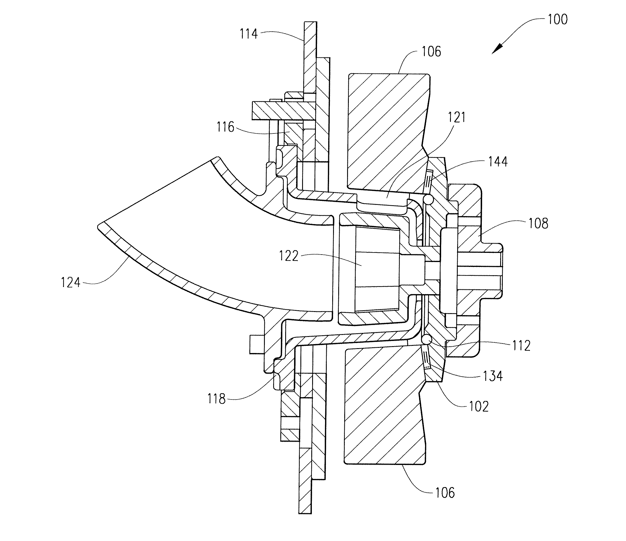
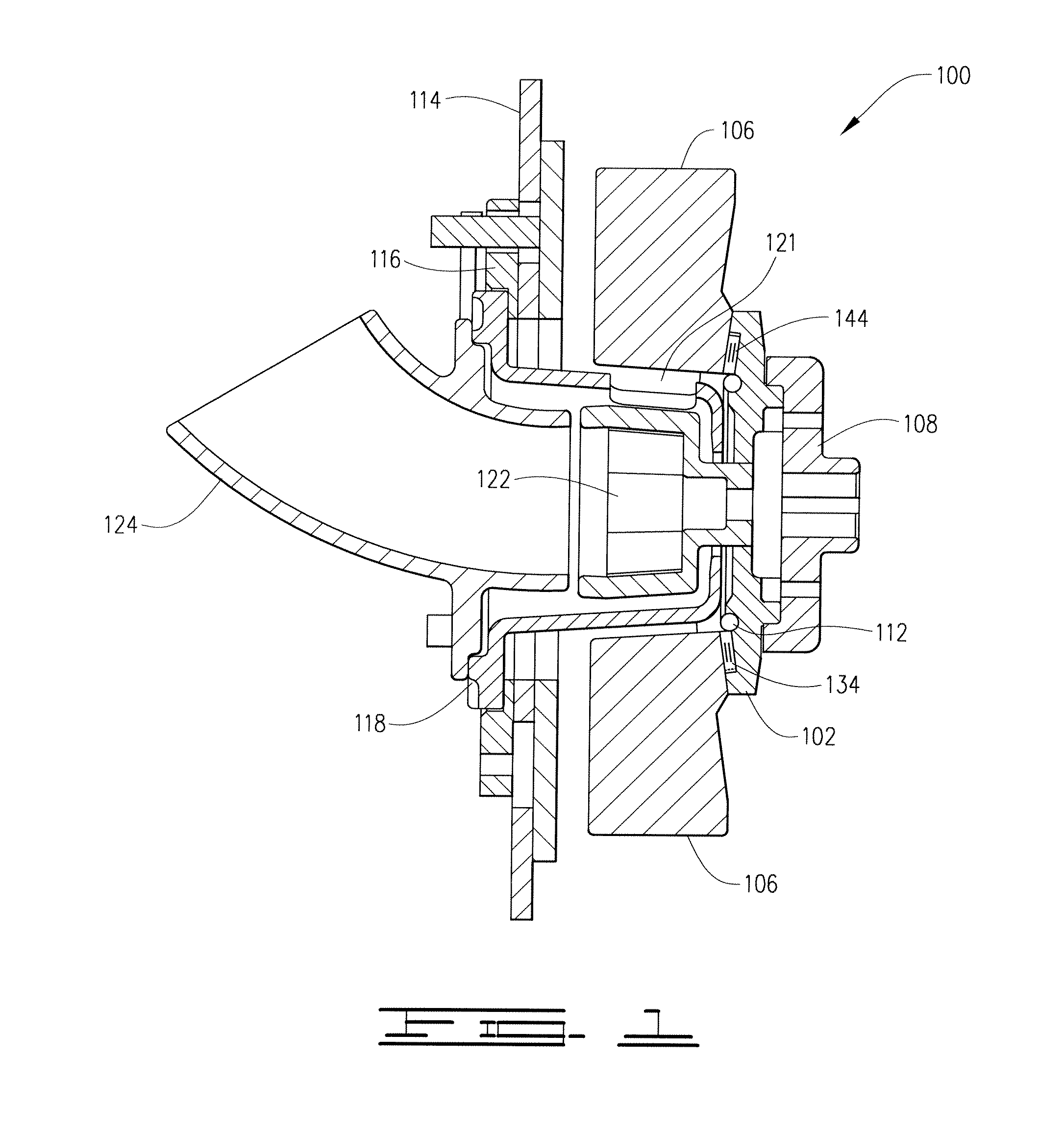
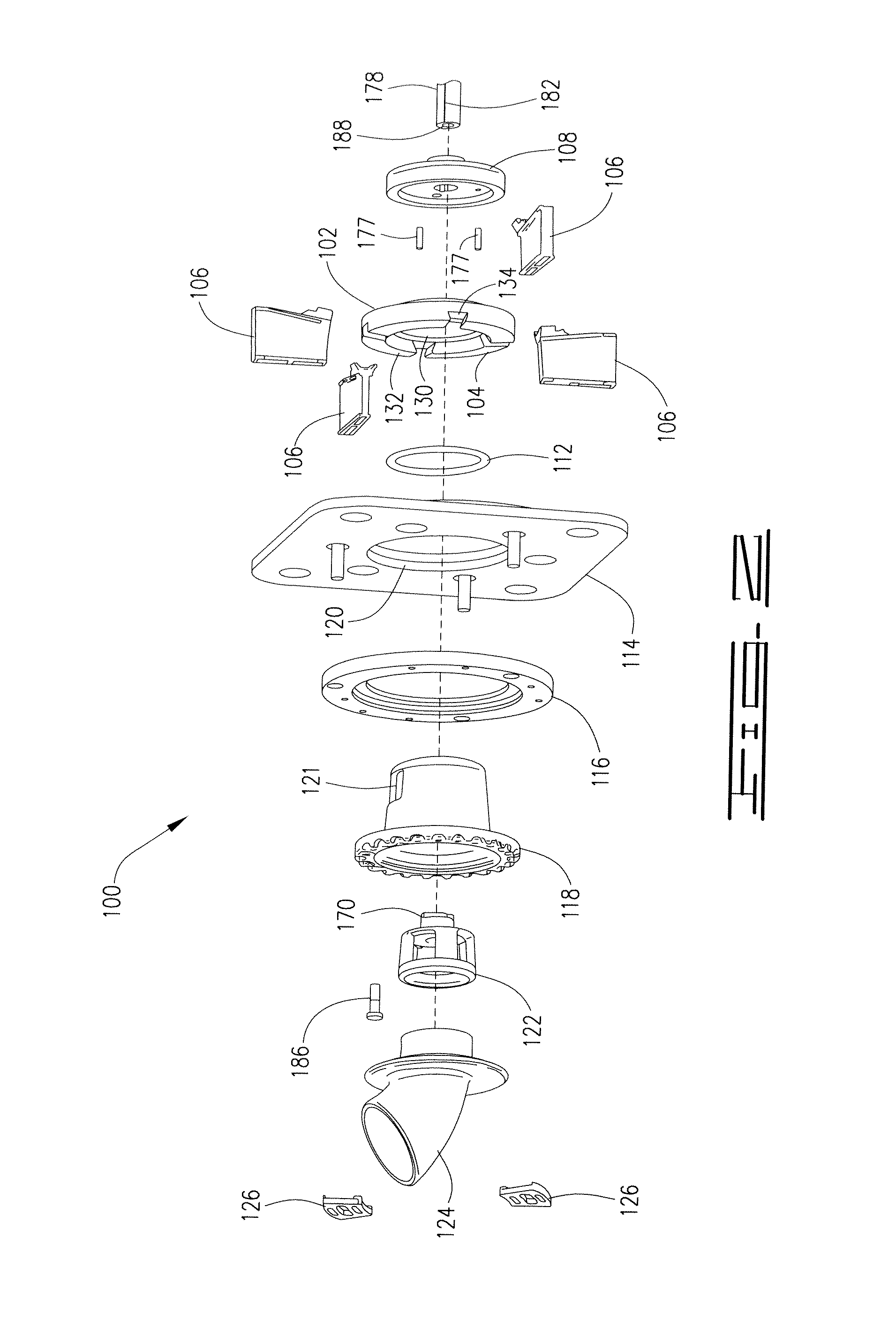
[0023]An embodiment 100 of the inventive throwing wheel assembly is depicted in FIGS. 1-9. The inventive assembly 100 comprises: a single plate throwing wheel 102 having a forward face 104; a plurality of throwing blades 106 which are removably positionable on the wheel face 104; an assembly hub 108 which is positioned on the rearward side 110 of the rotating wheel 102; an O-ring or other retainer 112 for preventing the throwing blades 106 from falling off of the wheel face 104 during installation; a mounting plate 114 which forms a part of the housing of the blasting system for aligning and securing the various components of the inventive assembly 100; a control cage adaptor 116 which is installed on the forward face of the mounting plate 114; an adjustable control cage 118 which extends through a central aperture 120 of the mounting plate 114 and includes a side discharge opening 121 for controlling the point of delivery of the abrasive material to the inlet ends of the throwing b...


PUM

PropertyMeasurementUnit
Angleaaaaaaaaaa
Angleaaaaaaaaaa
Angleaaaaaaaaaa

Abstract

An abrasive throwing wheel assembly comprising a rotating wheel having a forward face including: a recess bounded circumferentially by an interior wall of a forward peripheral portion; a plurality of blade slots in the forward peripheral portion; and a groove, for receiving a retaining element, provided in the recess proximate the rearward base end of the interior wall. To prevent the retaining element groove from interfering with the attachment and removal of the blades, the assembly also includes: (a) the peripheral portion having a rearwardly sloped forward surface, (b) the interior wall diverging rearwardly toward the axis of rotation, and / or (c) the blade slots extending outwardly from the recess at a rearward angle.

Description

FIELD OF THE INVENTION[0001]The present invention relates to throwing wheel assemblies for abrasive blasting machines.BACKGROUND OF THE INVENTION[0002]Centrifugal blasting machines are commonly used for stripping or cleaning floors, storage tank walls, metal castings, and other items. Some machines employ a throwing wheel assembly comprising a plurality of throwing blades mounted on only the front face of a single plate-type rotor, runner head, or other single plate wheel element. Other designs utilize wheels having a pair of opposing plates (i.e., a front plate and a back plate) between which the throwing blades are mounted. Although the single plate and double plate designs all have limited service lives, the single plate-type wheel designs are preferred by many in the art because they are simpler and much less costly to manufacture, balance, and replace.[0003]The blasting machine throwing blades are adapted for receiving a stream of steel shot, hardened steel grit, other abrasive...

Claims


Application Information

Patent Timeline
IPC IPC(8): B24C5/06
CPCB24C5/062
Inventor GOFF, JAMES R.
Owner BLAST CLEANING TECH INC
Why Eureka
Try Eureka