Method and plant for removing carbon dioxide from flue gas

a technology of flue gas and carbon dioxide, which is applied in the direction of combustion process, inorganic chemistry, combustion treatment, etc., can solve the problems of requiring energy, difficult to retrofit cosub>2/sub>-handling equipment in existing, and the primary process of the plant, the cosub>2/sub>-generating process, and the inefficiency of the cosub>2/sub>-generating process. to achieve the effect of reducing energy costs

Inactive Publication Date: 2011-10-25
CO2 NORWAY +1
View PDF13 Cites 37 Cited by
  • Summary
  • Abstract
  • Description
  • Claims
  • Application Information

AI Technical Summary

Benefits of technology

[0016]The main object of this invention is to provide a method and a plant for reducing the energy costs associated with capture and separation of CO2 from a gas phase by the use of conventional gas absorption technology.
[0017]Another object is to provide a method and a plant for capture and separation of CO2 from a gas phase which can easily be retrofitted to existing CO2-generating processes or plants.
[0018]Another object is to reduce the need for external heat for heating the desorption column of amine-based purification plants.

Problems solved by technology

The major drawback with an amine plant is that it requires energy.
This makes it difficult to retrofit CO2-handling equipment in existing CO2-generating plants without switching off the whole plant during reconstruction of the heat recovery steam generator.
Another disadvantage is that the primary process of the plant, the CO2-generating process, will be less efficient since energy in the form of hot steam is extracted for use in the desorption column (but the complete process including this will be more efficient).
In addition to this, an integrated primary CO2-generating process and CO2-capture process means that both processes have to be run as a single process, resulting in less flexibility and lower on-line factor for the complete complex compared with the CO2-generating process alone.
This consequence is generally considered to be so unfavourable as to make it preferable to reduce the total energy efficiency and instead obtain the hot steam required for running the desorption column from an external steam source.
The penalty in the form of energy loss for running the primary CO2-generating process and CO2-handling process as two separate processes is substantial.
Thus there is a substantial energy loss associated with handling of greenhouse emissions from combustion gases and a corresponding need for more efficient methods of performing stripping of the combustion gases.

Method used


Image

  • Method and plant for removing carbon dioxide from flue gas
  • Method and plant for removing carbon dioxide from flue gas
  • Method and plant for removing carbon dioxide from flue gas

Examples


Embodiment Construction

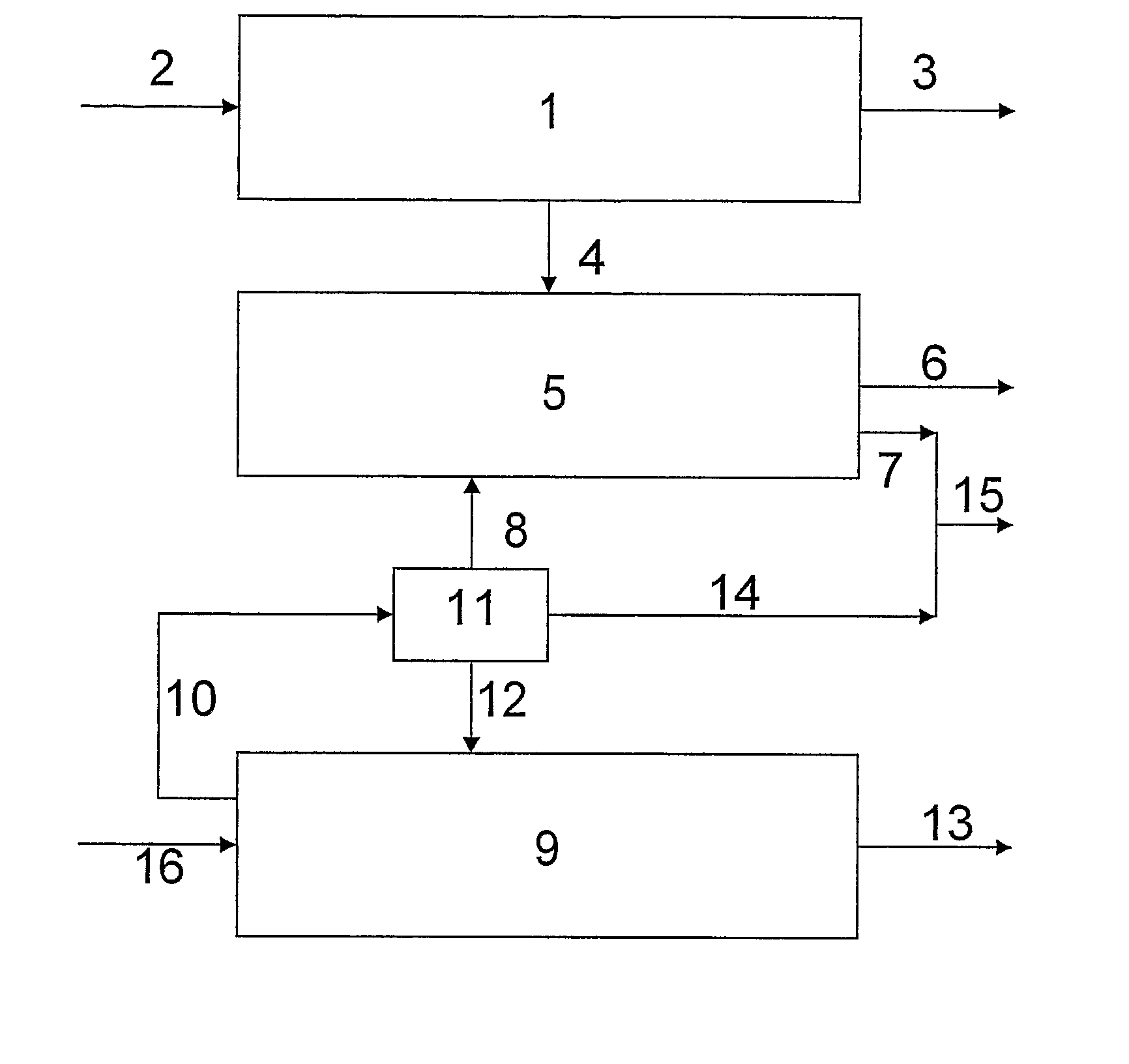
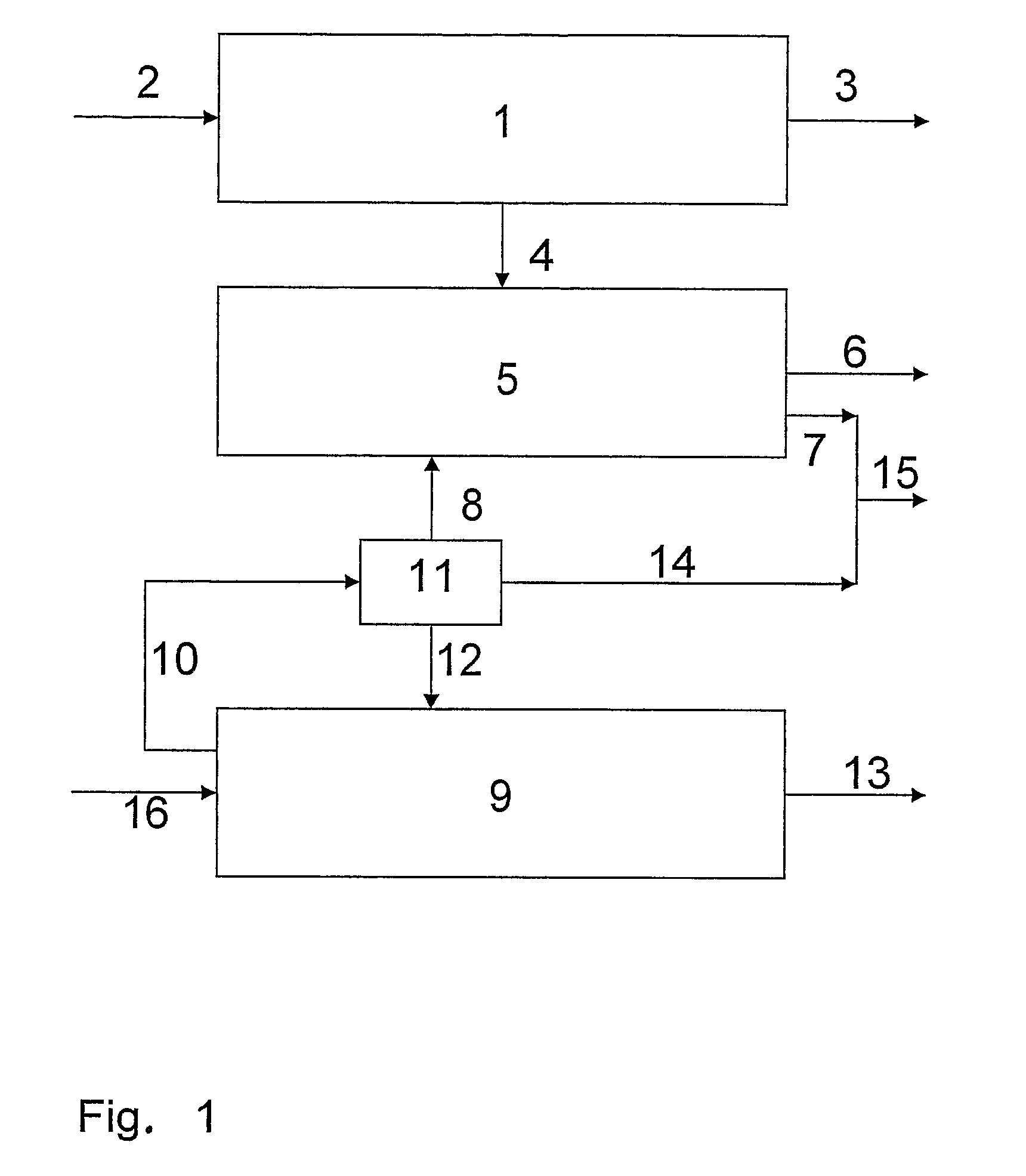
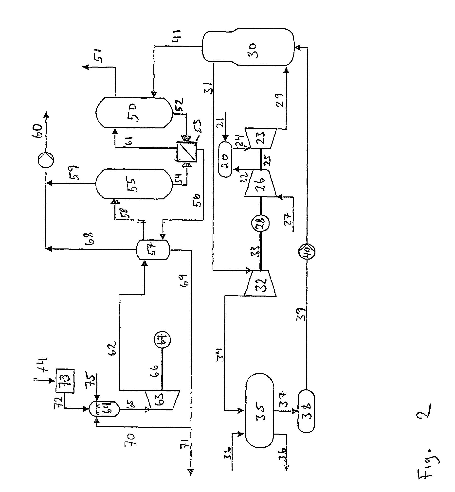
[0035]The invention will now be described in greater detail in the form of a preferred embodiment illustrated schematically in FIG. 2.

[0036]In the preferred embodiment of the invention the primary CO2-generating process is a power plant of the type “natural gas combined cycle” (NGCC). From the technical point of view the invention can function almost equally well with all types of the above-mentioned primary processes, but for marketing reasons the so-called “natural gas combined cycle”—gas power plant is preferred as the primary CO2-generating process in this invention.

[0037]For handling CO2 in the flue gas from the NGCC plant, the use is preferred of a conventional amine-based scrubber plant comprising one or more absorption and desorption columns for CO2 capture and separation. This technology has been chosen since it is a relatively cheap, well-proven and functional technology which manages to separate 85 to 90% of CO2 in the flue gas from the NGCC plant.

[0038]A preferred second...


PUM

PropertyMeasurementUnit
pressureaaaaaaaaaa
temperatureaaaaaaaaaa

Abstract

This invention relates to a method and plant for energy-efficient removal of CO2 from a gas phase by means of absorption. The invention is particularly suitable for use in connection with thermal power plants fired by fossil fuels, and is also well-suited for retrofitting in existing thermal power plants. A processing plant according to the invention comprises three sections: a primary CO2-generating process that serves as main product supplier; a CO2-capture and separation plant based on absorption and desorption of CO2 respectively by / from at least one absorbent; and a second CO2-generating process where combustion of carbonaceous fuel in pure oxygen atmosphere serves as energy supply to at least a part of the thermal energy necessary to drive the regeneration of the absorbent in the desorption column(s).

Description

[0001]This invention relates to a method and plant for energy-efficient removal of CO2 from a gas phase by means of absorption. The invention is particularly suitable for use in connection with thermal power plants fired by fossil fuels, and is also well-suited for retrofitting in existing thermal power plants.THE BACKGROUND TO THE INVENTION[0002]For almost 100 years fossil fuels have been man's most important energy source. At the present time fossil fuels cover approximately ⅘ of the world's energy consumption, and there is hardly any sector of society in the industrialised countries today that is not dependent on fossil fuels as energy carrier including the energy sector where the electricity supply in many countries is largely based on thermal power plants fuelled by coal, oil or natural gas.[0003]Fossil fuels are remains of ancient biological material which has been converted to pure carbon structures and / or hydrocarbons in certain types of geological formations. Due to the fac...

Claims


Application Information

Patent Timeline
Patent Type & Authority Patents(United States)
IPC IPC(8): B01D53/62B01D53/14B01D53/34
CPCB01D53/1418B01D53/1425B01D53/1475Y02C10/04Y02C10/06Y02E20/16Y02A50/20Y02C20/40
Inventor HUSTAD, CARL W.TRONSTAD, INGO
Owner CO2 NORWAY
Why Eureka
Try Eureka