Light emitting diode submount with high thermal conductivity for high power operation

a technology of high thermal conductivity and diodes, which is applied in the direction of conductive pattern formation, printed circuit assembling, point-like light sources, etc., can solve the problems of high heat generation, high production cost, and high electrical insulation requirements in many applications, and achieve good electrical insulation, high thermal conductivity, and good electrical insulation

Active Publication Date: 2011-10-25
DICON FIBEROPTICS
View PDF17 Cites 9 Cited by
  • Summary
  • Abstract
  • Description
  • Claims
  • Application Information

AI Technical Summary

Benefits of technology

[0007]In one embodiment of this invention, a LED chip is bonded to a supporting structure that comprises at least two different layers of anodized aluminum oxide: a porous layer and a non-porous layer. By employing a porous layer and a non-porous layer of anodized aluminum oxide, it is possible to achieve at least some of the above noted desirable and preferred features. Thus, the supporting structure can provide high thermal conductivity and good electrical insulation, while also providing the smooth morphology and mechanical strength that are also preferable features of the LED submount.

Problems solved by technology

However, in order for high-power LEDs to achieve the high lumens output and flux density (as a white light source) that is needed to replace conventional technologies such as incandescent bulbs, fluorescent lighting, and metal halide light sources, the LEDs must be driven at high current levels, which in turn results in high levels of heat generation.
Although some LED applications allow the use of electrically-conducting submount or substrate materials, electrical insulation (high electrical resistance, or low electrical conductivity) is required in many applications.
Therefore, the development of a high thermal conductivity LED submount or substrate materials that also provides superior electrical insulation, is one of the key issues for addressing LED heat dissipation.
However, the complicated process and high production cost will limit the application of these materials.

Method used


Image

  • Light emitting diode submount with high thermal conductivity for high power operation
  • Light emitting diode submount with high thermal conductivity for high power operation
  • Light emitting diode submount with high thermal conductivity for high power operation

Examples


embodiment 1

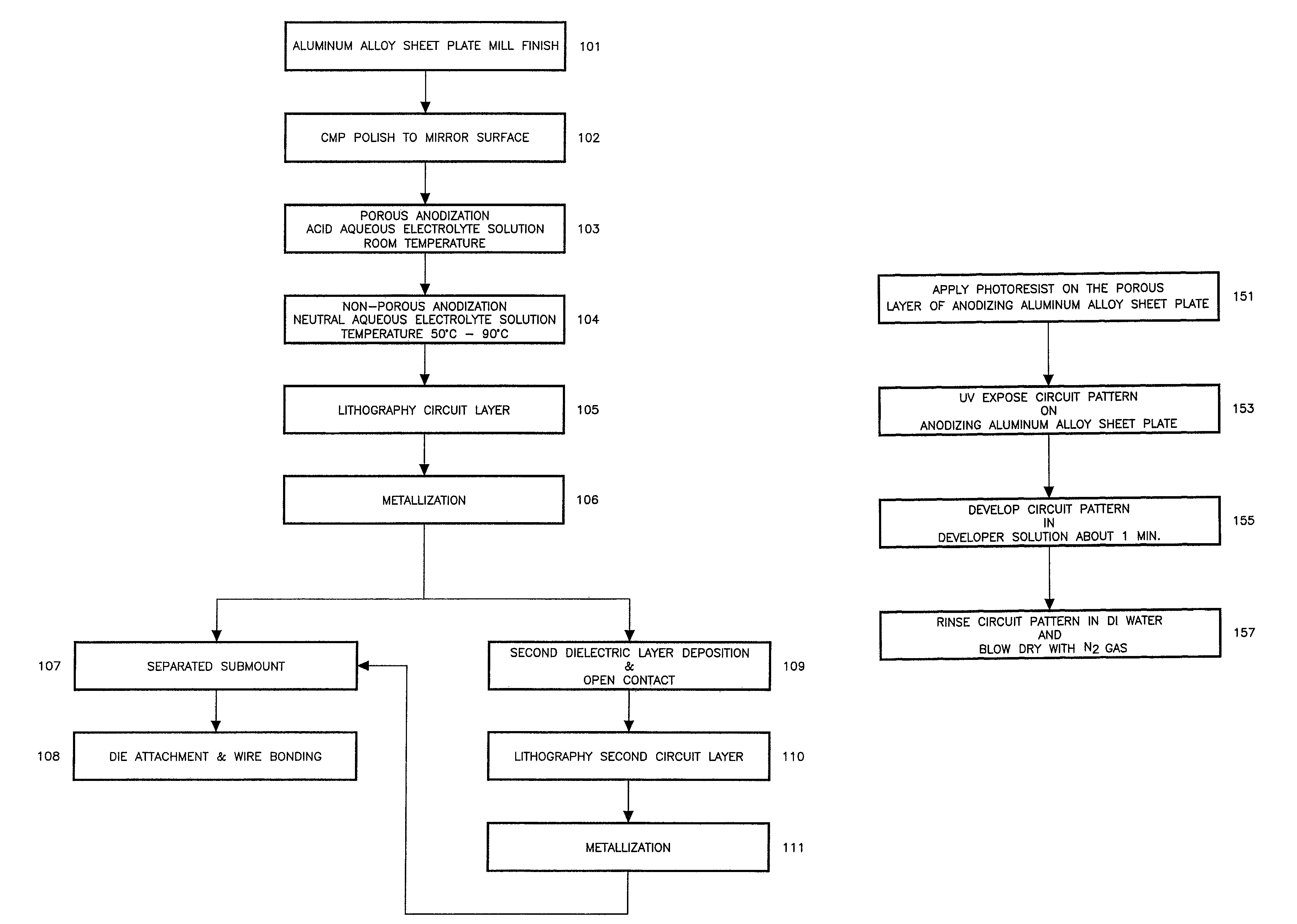
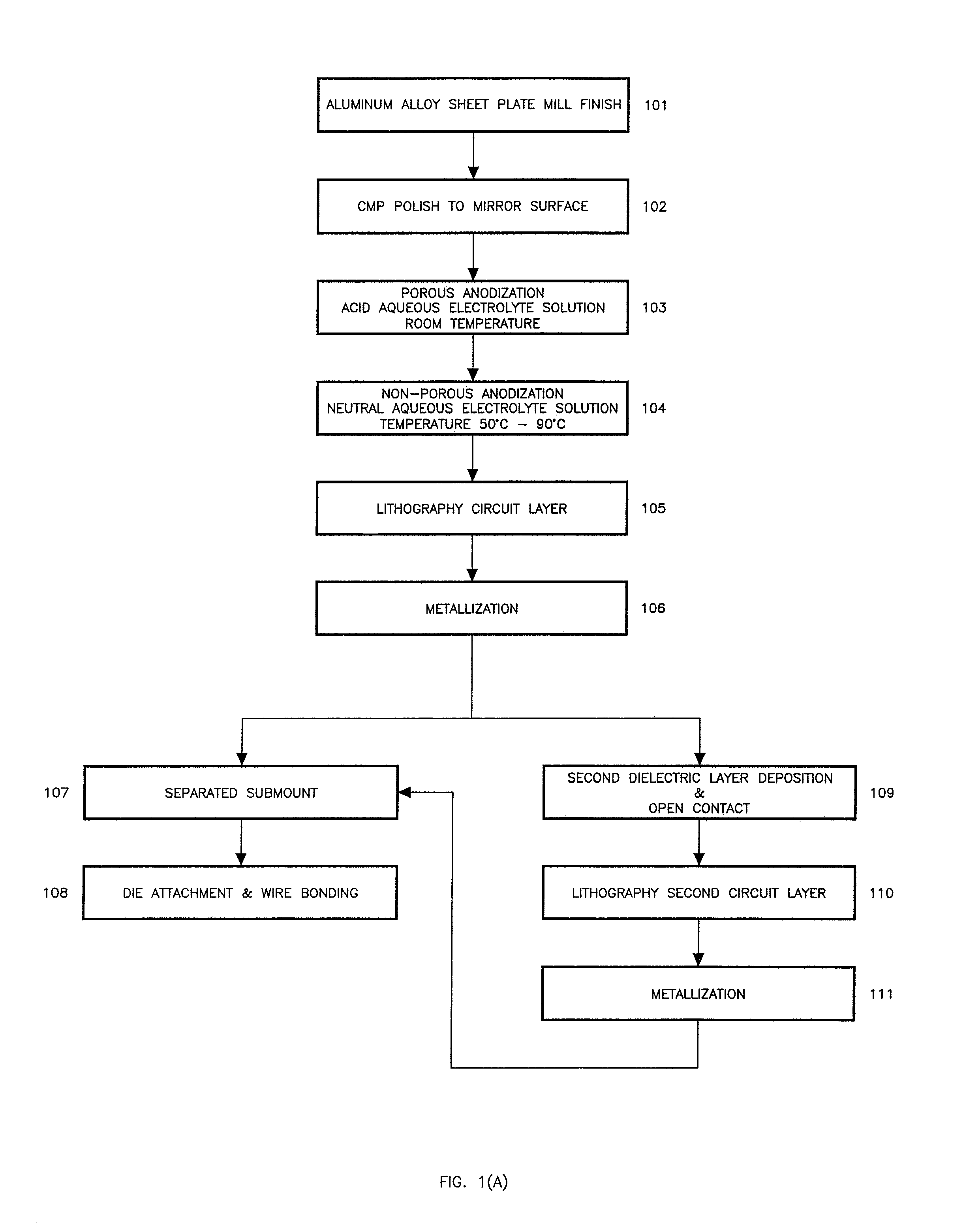
[0033]Embodiment 1 of the present invention, is illustrated in FIG. 1(A) as a process flow chart for the anodizing of a commercial aluminum alloy sheet plate 1100 that contains a minimum of 99% aluminum of thermal conductivity 222 W / m°K, with mill finish 101. The aluminum alloy sheet plate is first degreased in boiling acetone and then rinsed in running de-ionized (DI) water (block 101). A mixed chemical solution from FUJIMI'S PLANERLITE 7000™ polishing slurry series is then used for CMP (chemical mechanical polishing) (block 102). The surface of the aluminum alloy sheet plate is polished until a mirror finish is achieved, and the RMS value of surface roughness is less than 10 nm, as verified by using a KLA-Tencor P-10 surface profile measurement for a length of 300 μm. The structure resulting from steps 101 to 108 will comprise the aluminum alloy sheet plate and the following layers in the order of increasing distance from the aluminum alloy sheet plate: a layer of non-porous alumi...

embodiment 2

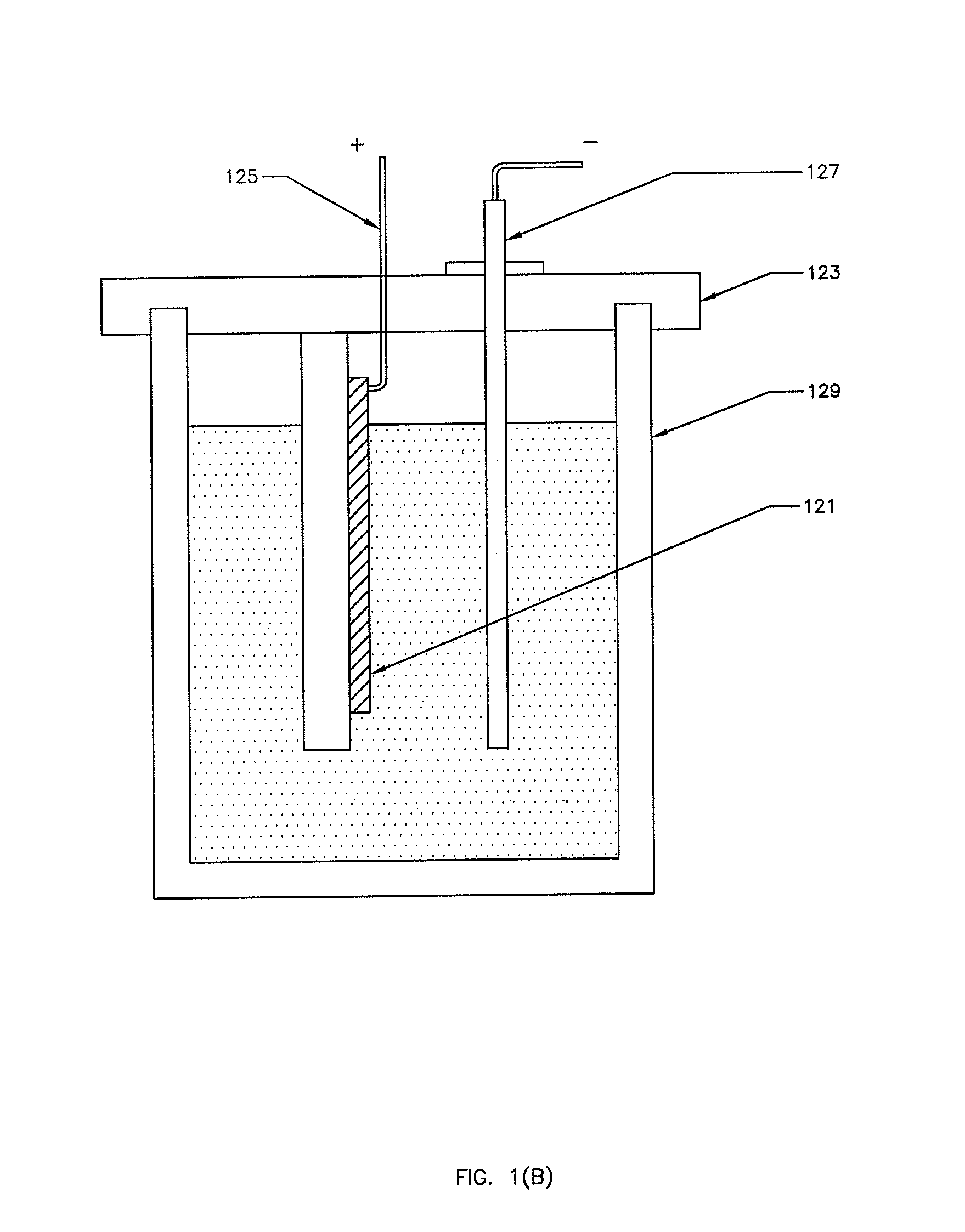
[0043]In Embodiment 2 of the present invention, the aluminum alloy sheet plate 201 has been processed through the chemical mechanical polishing (CMP) step, and the RMS value of the surface roughness is less than 10 nm. The porous oxide layer 203 is grown under aqueous sulfuric acid of wt less than 10% and constant current density of 2.80 mA / cm2, at room temperature for 15 minutes. The non-porous oxide layer 202 is accomplished by use of a neutral aqueous ammonium pentaborate solution of wt 4-10%, at bath temperature less than 90° C. To avoid electrical discharge in the electrolyte solution, a constant voltage of 270 V is applied to the sample. At the beginning of this process the maximum current density is 2.34 mA / cm2, decreasing to 0.25 mA / cm2 by the end of the process. A transition layer 204, which has poorer electric insulator characteristics, is a mixed phase of porous and non-porous oxides. To avoid blocking the thermal path from the LED die, a thin dielectric layer 205, with t...


PUM

PropertyMeasurementUnit
temperatureaaaaaaaaaa
total thicknessaaaaaaaaaa

Abstract

This invention relates to the thermal management, extraction of light, and cost effectiveness of Light Emitting Diode, or LED, electrical circuits. An integrated circuit LED submount is described, for the packaging of high power LEDs. The LED submount provides high thermal conductivity while preserving electrical insulation. In particular, a process is described for anodizing a high thermal conductivity aluminum alloy sheet to form a porous aluminum oxide layer and a non-porous aluminum oxide layer. This anodized aluminum alloy sheet acts as a superior electrical insulator, and also provides surface morphology and mechanical properties that are useful for the fabrication of high-density and high-power multilevel electrical circuits.

Description

BACKGROUND OF THE INVENTION[0001]Over the past several decades, the performance of light emitting diodes (LEDs) has increased in many ways, including improvements in efficiency, flux output, color rendering, stability of color, and stability of the correlated color temperature of white light. These improvements, and the high reliability of LEDs, make them useful for a wide range of high-brightness illumination applications, including automotive forward lighting and various display applications. However, in order for high-power LEDs to achieve the high lumens output and flux density (as a white light source) that is needed to replace conventional technologies such as incandescent bulbs, fluorescent lighting, and metal halide light sources, the LEDs must be driven at high current levels, which in turn results in high levels of heat generation. Special packaging techniques need to be employed to prevent the degradation of LED quantum efficiency, due to temperature increases. Although s...

Claims


Application Information

Patent Timeline
Patent Type & Authority Patents(United States)
IPC IPC(8): H01L33/00H01L33/48H01L33/60
CPCH01L33/005H01L33/60H05K1/053H01L33/483Y10T29/4913H05K1/162H05K1/183H05K2201/0116H05K2201/0179H05K2201/10106H05K2203/0315Y10S362/80H01L2924/19107H01L2224/45144Y10T29/49149Y10T29/53113Y10T29/49155H01L2224/13H01L2224/48091Y10T29/49144Y10T29/49147H01L2924/00014H01L2924/00
Inventor SU, WEN-HERNGLU, JUNYINGLEE, HO-SHANG
Owner DICON FIBEROPTICS
Why Eureka
Try Eureka