Location detection apparatus

a technology of location detection and detection apparatus, which is applied in the direction of active open surveying means, instruments, measurement devices, etc., can solve the problems of increasing the size of the resolver and the rotary encoder and so as to achieve the effect of reducing the size and weight, reducing the size of the range sensor

Inactive Publication Date: 2011-10-25
NIPPON SOKEN +1
View PDF5 Cites 0 Cited by
  • Summary
  • Abstract
  • Description
  • Claims
  • Application Information

AI Technical Summary

Benefits of technology

[0008]In view of the above and other difficulties, it is an objective of the present invention to provide a location detection apparatus capable of having a small and simple configuration.
[0010]According to the above location detection apparatus, since the location detection apparatus includes the above-described second light receiving element and the above-described light conductor, the second light receiving element can well receive the light each time the rotational position of the light output side reflector becomes the predetermined position. It is therefore possible to detect a reference position without employing a complicated configuration, the reference position providing a reference for the detecting of the rotational position. Moreover, since the rotational position of the light output side reflector is detected based on the detection result of the second light receiving element or a result of the detection of the reference position, it is possible provide a simplified and downsized configuration for detecting the rotational position of the light output side reflector, and as a result, it is possible to provide the location detection apparatus with a smaller size and a lighter weight as a whole.
[0012]According to the above location detection apparatus, it is possible to detect a reference position without employing a complicated configuration, the reference position providing a reference for detecting the rotational position. In particular, since the light receiving element can play both roles in detecting the object in the space and in detecting the reference position, it is possible to further simplify a configuration for detecting the rotational position of the light output side reflector, and as a result, it is possible to provide a location detection apparatus with a smaller size and a lighter weight as whole.

Problems solved by technology

According to the technique disclosed in the Patent Document 1, however, rotational position of the light reception mirror is detected by a resolver or a rotary encoder, which brings a difficulty associated with an increase in size of the range sensor.
Thus, there arises a difficulty associated with an increase in size of the resolver and the rotary encoder, and inhibition of the range sensor from having a smaller size and lighter weight as a whole.

Method used


Image

  • Location detection apparatus
  • Location detection apparatus
  • Location detection apparatus

Examples


first embodiment

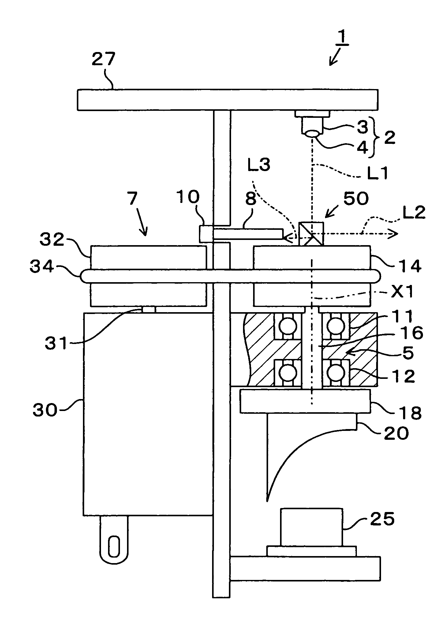
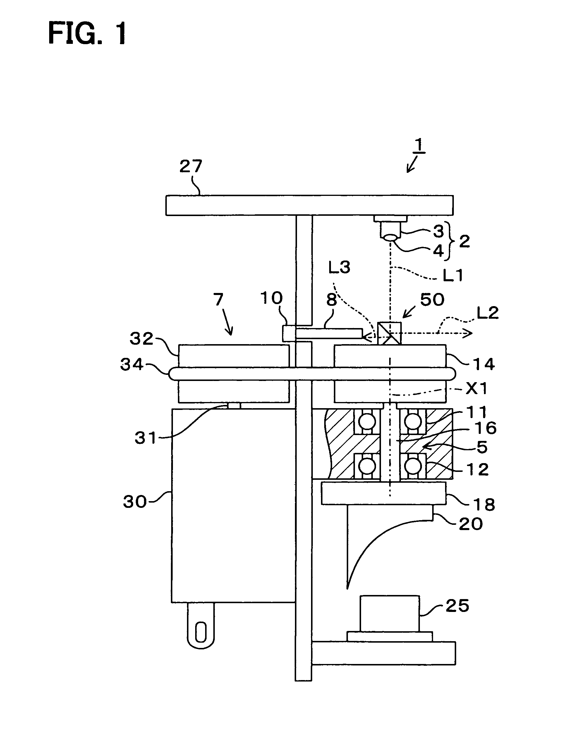
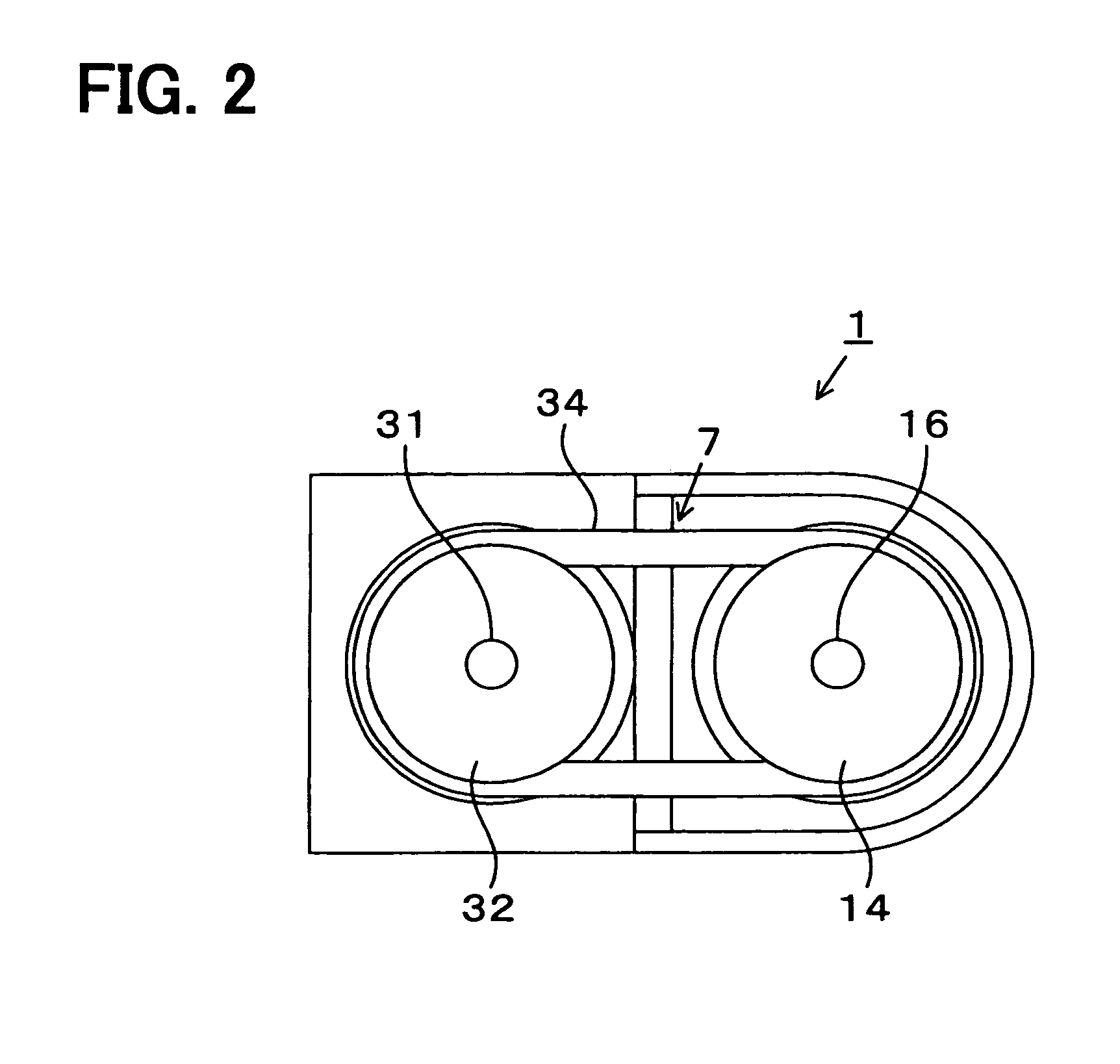
[0022]A first embodiment is described below. FIG. 1 illustrates a location detection apparatus according to the first embodiment. FIG. 2 illustrates a transmission mechanism of a location detection apparatus. FIG. 3 illustrates a beam splitter of a location detection apparatus and illustrates lights spited by the beam splitter. FIG. 4 illustrates the beam splitter that is rotated 180 degrees from the rotational position of the beam splitter 50 illustrate in FIG. 3.

[0023]As shown in FIG. 1, the location detection apparatus 1 according to the present embodiment includes a light source 2 and a beam splitter 50. The light source 2 outputs light L1 for detection. The beam splitter 50 has a reflecting surface 51a (see FIG. 3) for reflecting a part the light L1 from the light source 2 to a space. The light source 2 includes a laser diode 3 and a collective lens 4 for collecting a laser beam outputted from the laser diode 3. As the light L1 for detection, the collective lens 4 outputs the l...

second embodiment

[0051]A second embodiment is described below.

[0052]FIG. 5 illustrates a location detection apparatus 200 according to the second embodiment. The second embodiment is different from the first embodiment in that, in the second embodiment, a rotary encoder is attached to a drive axis 31 of a motor 30.

[0053]As shown in FIG. 5, the location detection apparatus 200 includes a circular plate 201. The circular plate 201 is attached to the drive axis 31 of the motor 30 and is rotatable integrally with the drive axis 31. The circular plate 201 may be a slit circular plate, which is used in a known rotary-encoder and has slits along an outer circumference thereof, wherein the splits are formed at predetermined intervals, for example, at 4 degrees angular intervals. A light output element and a light reception element (not shown) are disposed around the circular plate 201 to detect the slits. The rotary encoder of the location detection apparatus 200 includes the circular plate 201, the light o...

third embodiment

[0056]A third embodiment is described below.

[0057]FIG. 6 illustrates a location detection apparatus 300 according to the third embodiment. A location detection apparatus of the third embodiment is different from that of the first embodiment in that, for example, the beam splitter 50 is replaced with a mirror 60. Like parts are referred by using like reference numerals between the first and third embodiments.

[0058]The location detection apparatus 300 includes the mirror 60, which is an example as a light output side reflector functioning as light outputs side reflecting means. A reflecting surface 60a of the mirror 60 is inclined at an angle of 45 degrees with respect to the rotation axis X1. In other words, an angle between the reflecting surface 60a and the optical axis of the light L1 is 45 degrees. The mirror 60 reflects the light L1 incident thereon so that a sum of an angle of incident and an angle of reflection is 90 degrees. Wherever the rotational position of the mirror 60 i...


PUM


Abstract

A location detection apparatus is disclosed that includes: a light source; a light output side reflector having a reflecting surface for reflecting light from the light source to a space; a rotation mechanism for rotating the light output side reflector; a first light receiving element for receiving the light reflected from an object existing in the space; a light reception side reflector for reflecting the light from the object to the first light receiving element; a second light receiving element for receiving the light from the light output side reflector; a light conductor for conducting the light reflected from or transmitted through the reflecting surface toward the second light receiving element when the light output side reflector is in a predetermined position; and a rotational position detector that detects rotational position of the light output side reflector based on a detection result of the second light receiving element.

Description

CROSS REFERENCE TO RELATED APPLICATION[0001]The present application is based on Japanese Patent Application No. 2008-221516 filed on Aug. 29, 2008, disclosure of which is incorporated herein by reference.BACKGROUND OF THE INVENTION[0002]1. Field of the Invention[0003]The present invention relates to a location detection apparatus.[0004]2. Description of Related Art[0005]Patent Document 1 proposes a range sensor as one technique for detecting a distance to and a direction to an object existing in an external space. The range sensor includes a light source, a projection mirror, a light reception mirror, and a light receiving element. The projection mirror and the light reception mirror are rotatable together. The light from the light source is incident on the projection mirror along a rotation axis, and the projection mirror reflects the incident light to the external space. Then, the light may be reflected by an irradiated object (i.e., an object to be detected) existing in the exter...

Claims


Application Information

Patent Timeline
Patent Type & Authority Patents(United States)
IPC IPC(8): G01B11/14
CPCG01C15/002G01S7/4811G01S7/4813G01S17/42G01S7/4817
Inventor ISOGAI, TOSHIKIMATSUOKA, HISANAGAMATSUURA, MITSUYASUFUJITA, MITSURUODA, MOTOI
Owner NIPPON SOKEN
Why Eureka
Try Eureka