Pipe joint arrangement

a pipe joint and pipe technology, applied in the direction of flexible pipes, rigid pipes, pipe supports, etc., can solve the problems of inconvenient today to implement an elongated pipeline, inconvenient to execute the washing process of a process apparatus, and the disruption of pipework, so as to reduce the investment cost, reduce the effect of service and maintenance operations and essentially the available state of the ar

Active Publication Date: 2011-11-01
HURSKAINEN AARNE
View PDF13 Cites 0 Cited by
  • Summary
  • Abstract
  • Description
  • Claims
  • Application Information

AI Technical Summary

Benefits of technology

[0008]A pipe joint arrangement according to the present invention has an objective to provide a decisive improvement regarding the above-described problems and to thereby raise essentially the available state of the art. In order to accomplish this objective, a pipe joint arrangement of the invention is principally characterized by comprising a joining piece, connectible with pipeline sections to be coupled with each other successively in the longitudinal direction and consisting of frame elements locked to each other in a longitudinal direction and having provided therebetween a swivel member with a substantially cylindrical or spherical swiveling face for enabling movement of the frame elements by rotating the same relative to each other with respect to one or more axes of rotation.
[0009]In amongst the most important benefits gained by a pipe joint arrangement of the invention should be mentioned the simplicity of its construction and the advantages resulting from its use, regarding especially reduced investment costs and less service and maintenance operations. The swivel member with a substantially cylindrical or spherical swiveling face makes it possible to change the relative longitudinal direction of pipelines coupled with a joining piece of the invention either in a single plane relative to one axis of rotation or else three-dimensionally e.g. relative to two axes of rotation orthogonal to each other. By virtue of the invention, it is thus very easy to install pipelines, which extend e.g. in several directions and which are further possible to implement in constructions rotating around their longitudinal axis by using preferably a joining piece designed in universal joint principle and by supplying the washing fluid to be carried along the pipeline by way of the interior of the joining piece by means of a flow passage present in its swivel member and connected by its opposite ends in a sealed manner to flow paths present in the opposite frame elements of the frame. As a result, the pipe joint arrangement of the invention enables first of all implementation, of integrally constructed, multi-directional pipelines e.g. in process washing purposes or else installation of various pipelines to render it possible to displace the same by flexing relative to one or more articulations e.g. when such a displacement is required by service or maintenance operations applied to the actual process apparatus.

Problems solved by technology

Such fixed pipelines call for a shutdown of the process and a disruption of the pipework in the event that, for any reason, a change of location for a pipework is desired.
However, a particularly outstanding problem today exists in association with fixed pipelines intended for process washing, in which context the purpose to wash an industrial process, such as a process apparatus included in the basic equipment of a pulp or paper mill, by means of a wash pipe present within the same and rotating e.g. around its longitudinal axis.
Especially in solutions of the above type it is inconvenient to execute the washing process for a process apparatus, which proceeds, according to the principle shown e.g. in FIG. 5, in several longitudinal directions.
Accordingly, it is inconvenient today to implement an elongated pipeline, especially as a process washing apparatus rotating around its longitudinal axis, having a mobility in several directions or else in anticipation of its required mobility, e.g. due to maintenance operations applied to the actual process apparatus .
In such cases, the required extra equipment currently results in expensive investments, plenty of necessary service and maintenance operations and required space.

Method used


Image

  • Pipe joint arrangement
  • Pipe joint arrangement
  • Pipe joint arrangement

Examples


Embodiment Construction

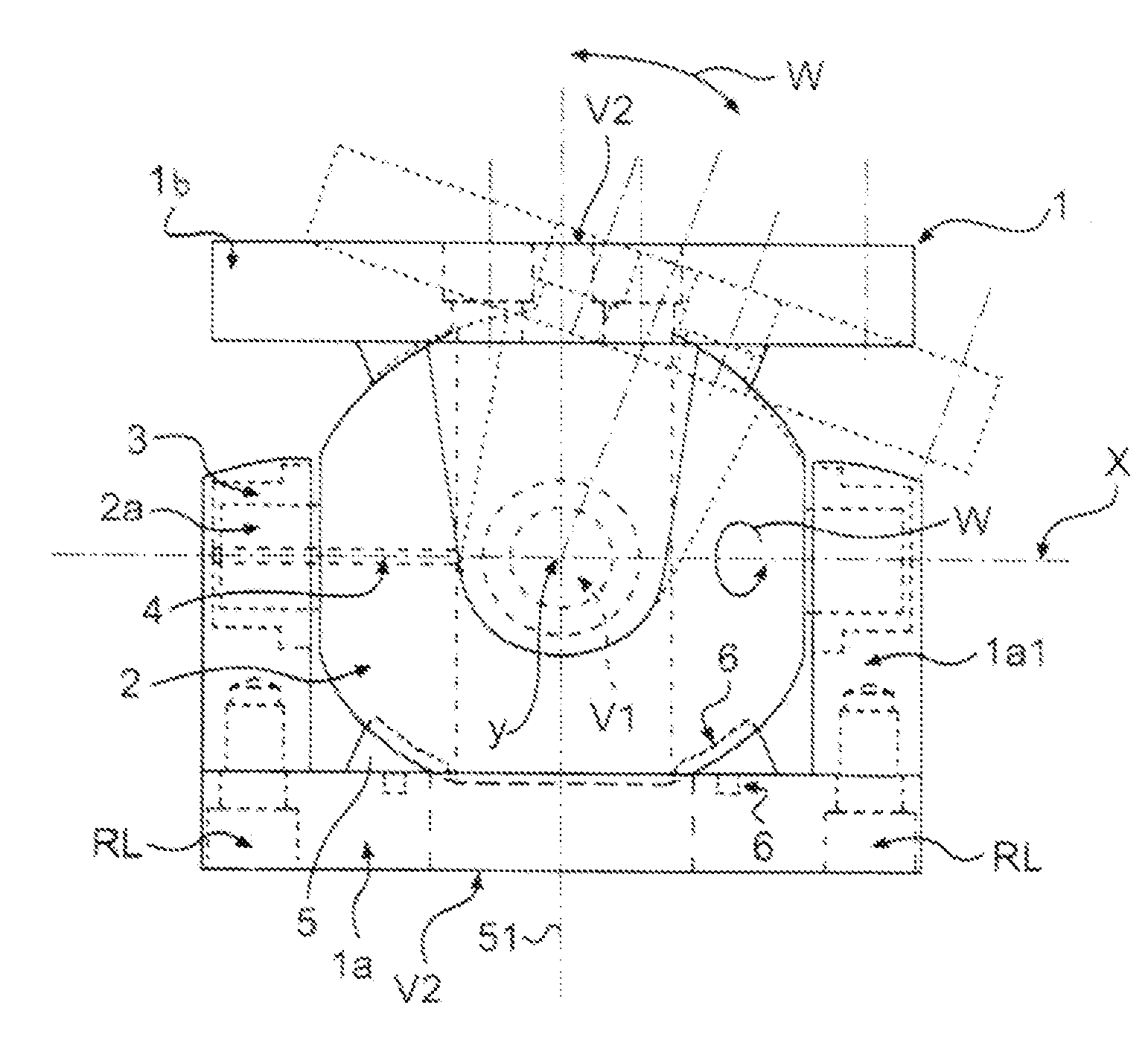
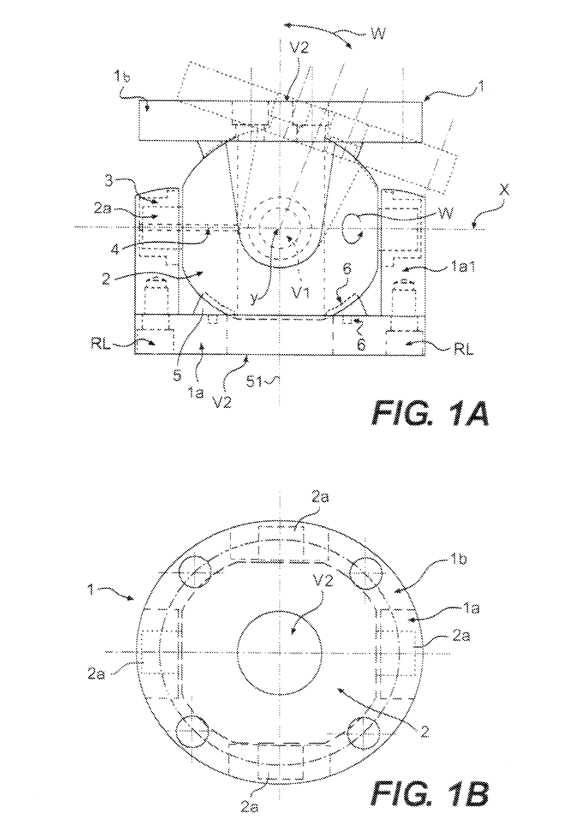
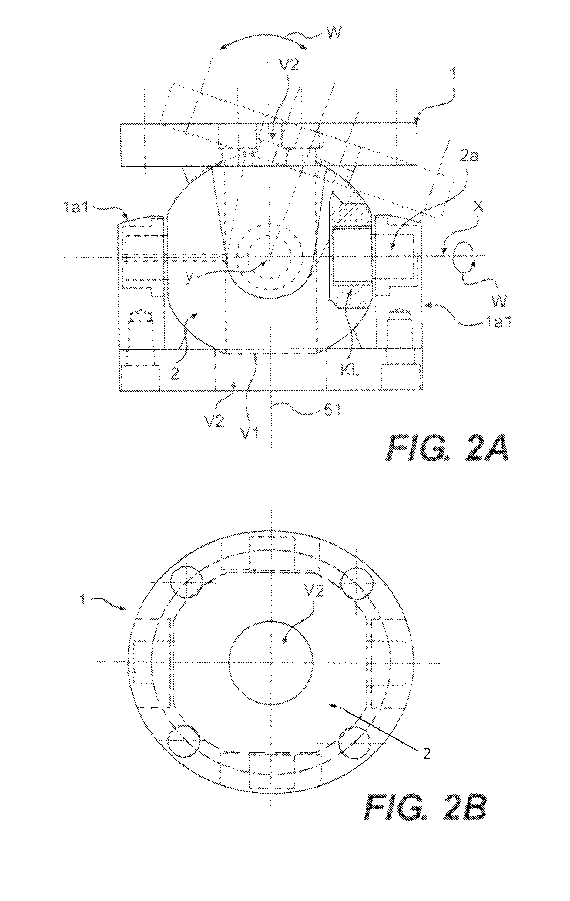
[0016]The invention relates to a pipe joint arrangement, which is intended for enabling one or more angular deflections successive in a longitudinal direction s along an elongated pipeline L in one or more planes . The pipe joint arrangement comprises, e.g. according to the principle shown in FIGS. 5a and 5b, a joining piece 1, connectible with pipeline sections to be coupled with each other successively in a longitudinal direction s1 and consisting of frame elements 1a, 1b locked to each other in the longitudinal direction s and having provided therebetween a swivel member 2 with a substantially cylindrical or spherical swiveling face for enabling movement of the frame elements 1a, 1b by rotating w the same relative to each other with respect to one or more axes of rotation.

[0017]FIGS. 1a and 1b, 2a and 2b, and 3a and 3b illustrate solutions pivotable symmetrically with respect to two axes of rotation x, y orthogonal to each other, wherein the swivel member 2 comprises a spherical ...


PUM


Abstract

A pipe joint arrangement, which is intended for enabling one or more angular deflections successive in a longitudinal direction along an elongated pipeline in one or more planes. A joining piece is connectible with pipeline sections to be coupled with each other successively in the longitudinal direction and includes of frame elements locked to each other in a longitudinal direction and provided therebetween a swivel member with a substantially cylindrical or spherical swiveling face for enabling movement of the frame elements by rotating the same relative to each other with respect to one or more axes of rotation.

Description

CROSS-REFERENCE TO RELATED APPLICATIONS[0001]This is the national phase under 35 U.S.C. §371 of PCT / FI2006 / 000307 filed 21 Sep. 2006.Field of the Invention[0002]The invention relates to a pipe joint arrangement, which is intended for enabling one or more angular deflections successive in a longitudinal direction along an elongated pipeline in one or more planes.BACKGROUND OF THE INVENTION[0003]In the above purpose it is currently conventional to employ fixed elbow pieces, e.g. in various process pipelines. Such fixed pipelines call for a shutdown of the process and a disruption of the pipework in the event that, for any reason, a change of location for a pipework is desired. However, depending on how the support of a pipework is arranged, it is in some cases possible to move a pipework sufficiently in operations calling for minor displacements.[0004]However, a particularly outstanding problem today exists in association with fixed pipelines intended for process washing, in which con...

Claims


Application Information

Patent Timeline
Patent Type & Authority Patents(United States)
IPC IPC(8): F16L27/04
CPCF16L27/023F16L27/04F16L27/0853F16L27/0857
Inventor HURSKAINEN, AARNE
Owner HURSKAINEN AARNE
Why Eureka
Try Eureka