Prosthesis fixation device and method

a technology of prosthesis and fixation device, which is applied in the field of prosthesis fixation device and method, can solve problems such as leakage around the stent gra

Inactive Publication Date: 2011-11-01
LIFESHIELD SCI +1
View PDF55 Cites 86 Cited by
  • Summary
  • Abstract
  • Description
  • Claims
  • Application Information

AI Technical Summary

Problems solved by technology

In the case of a stent graft, this may lead to leakage around the stent graft.

Method used


Image

  • Prosthesis fixation device and method
  • Prosthesis fixation device and method
  • Prosthesis fixation device and method

Examples


Embodiment Construction

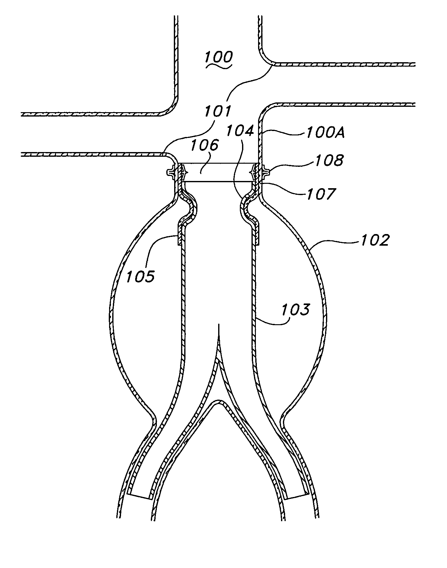
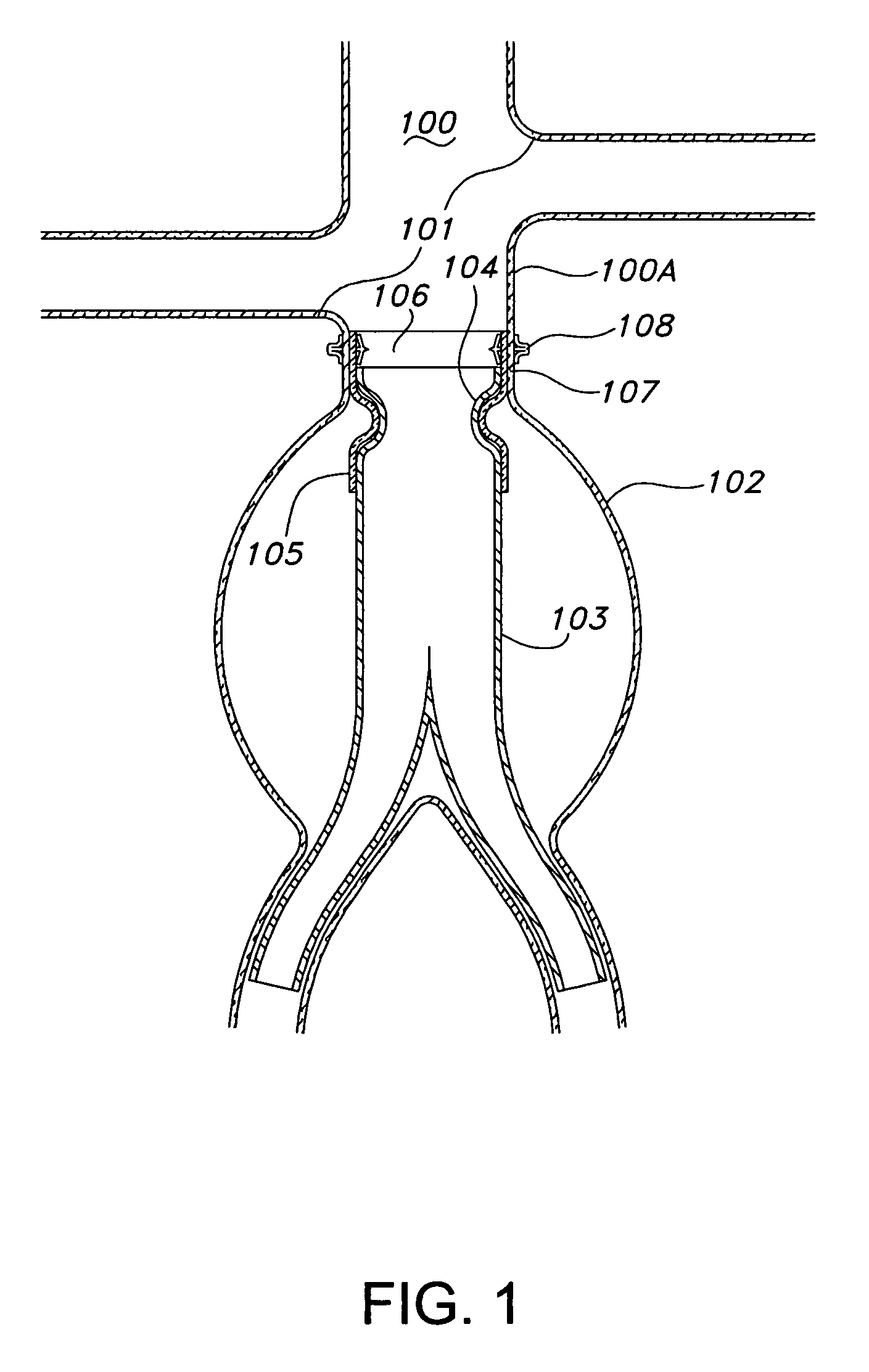
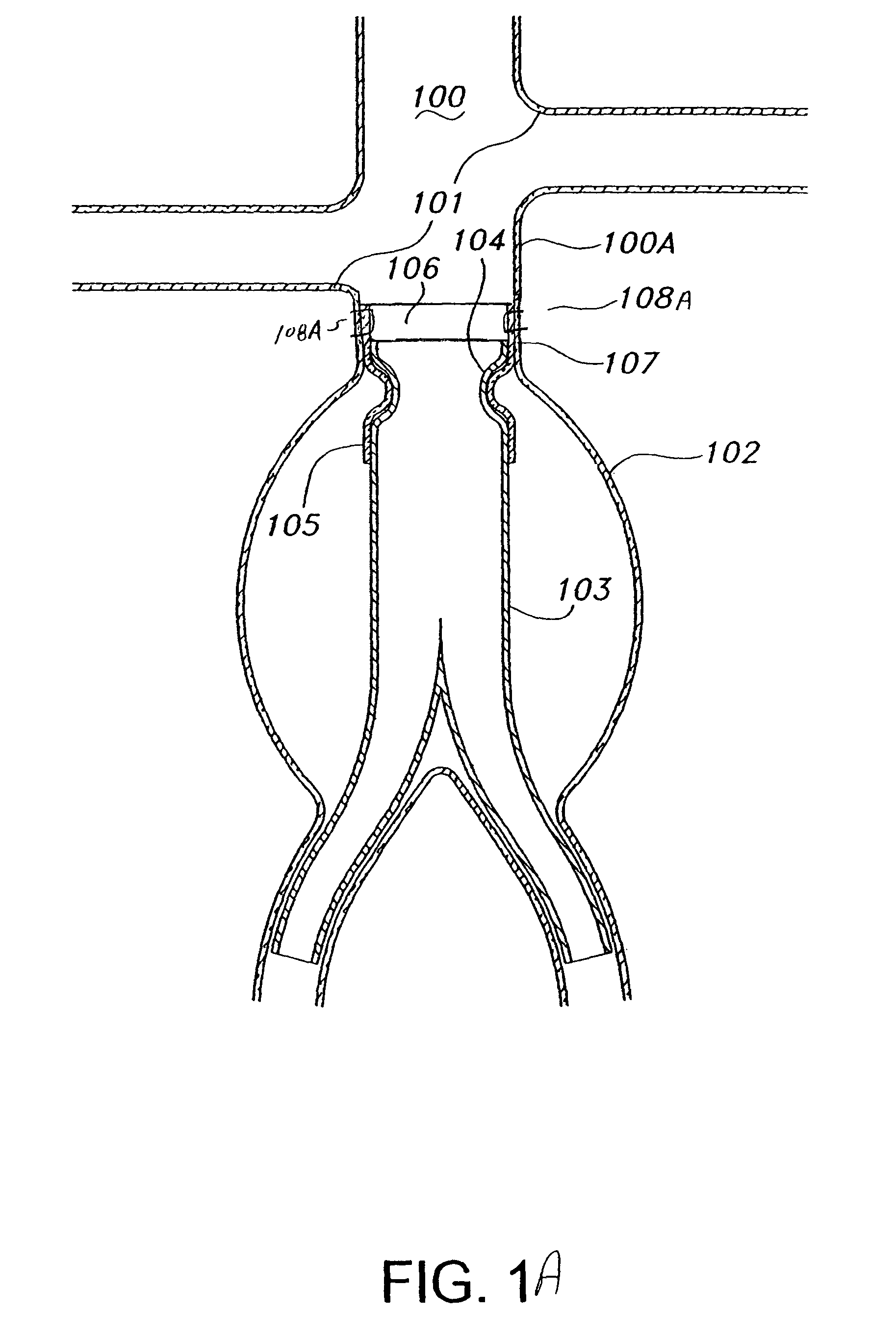
[0014]As shown in FIG. 1, an abdominal aorta 100 includes an aneurysm 102, located below renal arteries 101. Disposed just below renal arteries 101, the upper end 104 of a bifurcated stent graft 103 is affixed to the short undiseased length 100a of aorta 100 between renal arteries 101 and aneurysm 102 by engagement with a ridge defining an hour glass mating with a similar configuration in a mating docking section 105 of anchor 106. Anchor 106 also includes a landing section 107. Landing section 107 is attached to the aortic tissue above aneurysm 102 by double flat head fasteners 108 (as disclosed for example in U.S. Patent Application 2004 / 0044364 A1). Such fasteners include a shaft adapted to penetrate the landing section and an adjacent lumen wall with a flat head on each end thereof. The upper end 104 of stent graft 103 is thus firmly retained in mating docketing section 105 of anchor 106, and thereby in aorta 100, notwithstanding the relatively small amount of healthy tissue in ...


PUM


Abstract

A prosthesis anchor is adapted to convert a previously untreatable anatomy into a more typical and treatable condition. Preferably, the anchor is adapted to be transported endoluminally to a deployment site in a body lumen. The anchor includes a landing section for securing the anchor at a relatively fixed position in the lumen, and a docking section adapted to receive a mating prosthesis the landing section of the anchor may be permanently affixed to the lumen by a variety of mechanical and / or adhesive fixation means.

Description

BACKGROUND OF THE INVENTION[0001]Many medical conditions are treated by the implantation of a prosthesis in a body lumen. Such conditions include vascular stenosis and aneurysms and such prosthesis include stents and stent grafts. Increasingly, such prosthesis are deployed by endoluminal transport from a site remote from the deployment site. Fixation of the prosthesis at the deployment site is necessary to avoid displacement of the prosthesis. Stents are elongated devices, typically of a tubular skeletal metallic structure, with substantial elasticity. Stents may be used to support intraluminal walls and to exert a radial force on a constricted portion of a lumen wall to open a lumen to near normal size.[0002]A stent-graft typically includes tubular graft material affixed to the inside or outside of a stent and is delivered to the damaged site of a blood vessel via a catheter. Endoluminal stent-grafts, i.e. stent grafts delivered endoluminally, are often used to repair blood vessels...

Claims


Application Information

Patent Timeline
Patent Type & Authority Patents(United States)
IPC IPC(8): A61F2/82
CPCA61B17/064A61B17/068A61B17/11A61F2/07A61B2017/1107A61F2/848A61F2002/075A61F2002/8486
Inventor THISTLE, ROBERTDIMATTEO, KRISTIAN
Owner LIFESHIELD SCI
Why Eureka
Try Eureka