
Single inductor multiple output switching devices

a switching device and single inductor technology, applied in the direction of power conversion systems, instruments, dc-dc conversion, etc., can solve the problems of affecting the efficiency of the overall system, the effect of reducing cross regulation, and the overall system efficiency being poorer than ccm

Active Publication Date: 2011-11-01
CIREL SYST
View PDF7 Cites 28 Cited by
  • Summary
  • Abstract
  • Description
  • Claims
  • Application Information

AI Technical Summary

Benefits of technology

This approach reduces peak inductor current and minimizes cross-regulation across all loads and output voltage conditions, enhancing the overall efficiency of SIMO switching regulators in CCM operation.

Problems solved by technology

When a linear regulator is used as a DC to DC converter, there is an appreciable amount of power dissipation.
This enables support for higher load currents but for a given load current, the peak in the inductor current is higher and the efficiency of the overall system remains poorer when compared with CCM.
In a SIDO switching regulator operating in CCM, if the time slots for the two outputs are fixed, any disturbance caused to one sub-converter would cause a disturbance in the residual inductor current at the end of its time-slot.
Such a disturbance in residual current would further disturb the other sub-converter, thus resulting in cross-regulation.
This places a limit on the asymmetry of the two outputs and their load current that the converter can support without cross-regulation.

Method used


Image

  • Single inductor multiple output switching devices
  • Single inductor multiple output switching devices
  • Single inductor multiple output switching devices

Examples


Embodiment Construction

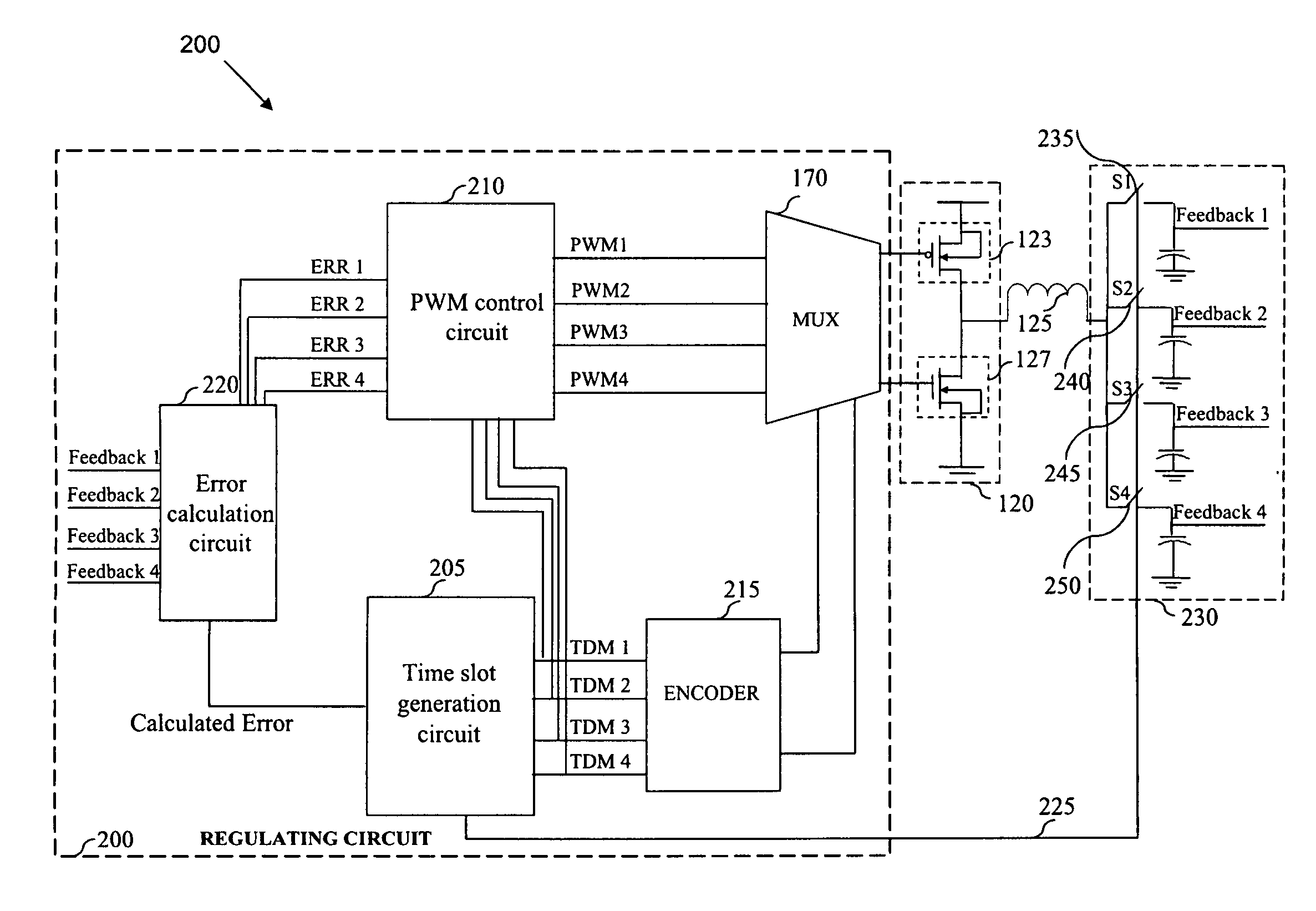
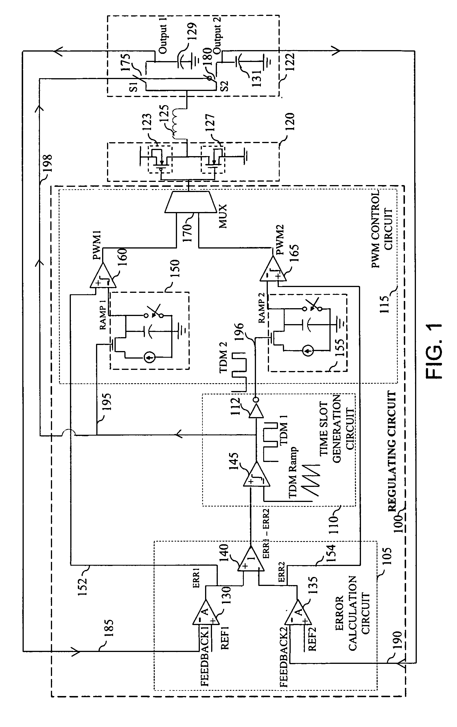
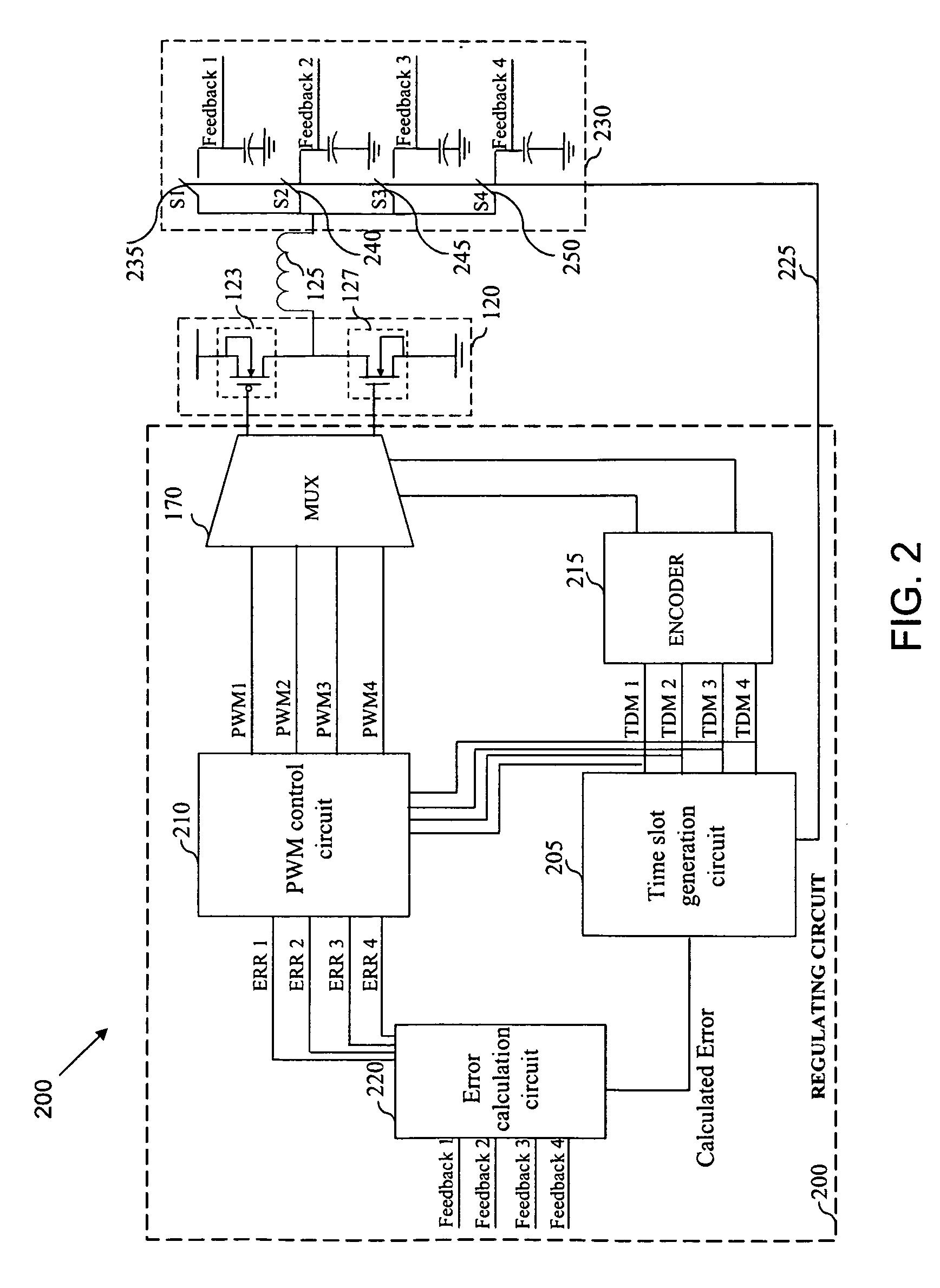
[0022]Embodiments of the invention described herein provide a system and method for regulating a single inductor multiple output (SIMO) switching device so as to minimize cross regulation. Various embodiments of the invention are explained using a switching regulator as an example of a switching device.

[0023]An embodiment of the invention provides a regulating circuit for SIMO switching regulators. In an embodiment of the invention, time slots for switching between the outputs in the SIMO switching regulator are controlled using pulse width modulation (PWM) errors in the outputs. This provides significant advantages in terms of cross regulation in continuous conduction mode (CCM) of operation of the SIMO switching regulator across all loads and output voltage conditions. Further, peak inductor current is minimized in CCM.

[0024]It will be appreciated that CCM operation of the SIMO switching regulator according to various embodiments of the invention is described only by way of illust...


PUM


Abstract

Single inductor multiple output (SIMO) switching devices with efficient regulating circuits. The SIMO switching device includes a plurality of time division multiplexing (TDM) switches for switching current through an inductor of the SIMO switching device. The plurality of TDM switches produces a plurality of outputs. The SIMO switching device further includes an error calculation circuit operatively coupled to the plurality of outputs for determining a calculated error from the plurality of outputs; a time slot generation circuit for controlling the plurality of TDM switches according to the calculated error; and a pulse width modulation (PWM) control circuit operatively coupled to the time slot generation circuit for controlling a plurality of PWM switches of a switching stage of the SIMO switching device in a continuous conduction mode (CCM) of operation. The PWM switches are controlled according to the time slots generated by the time slot generation circuit.

Description

BACKGROUND[0001]This patent application claims priority from Indian Non provisional patent application number 1830 / CHE / 2008, filed on Jul. 29, 2008 entitled “SINGLE INDUCTOR MULTIPLE OUTPUT SWITCHING DEVICES” and assigned to Cosmic Circuits Private Limited, 303, A Block, AECS Layout, Kundalahalli, Bangalore-560037, India, which is hereby incorporated in its entirety.FIELD[0002]Embodiments of the invention relate generally to switching devices and more particularly to regulating single inductor multiple output (SIMO) switching devices.PRIOR ART[0003]Many of today's battery powered consumer products require more than one power supply voltage level to operate. For example, a central processing unit (CPU) for a laptop may be designed to operate at 2.9 volts while the hard disk drive operates at 5 volts. Instead of providing several sources of power supply, these products typically use a single power supply source and generate other supply levels with DC to DC converters. The DC to DC co...

Claims


Application Information

Patent Timeline
Patent Type & Authority Patents(United States)
IPC IPC(8): G05F1/577
CPCH02M3/158H02M2001/009H02M1/009
Inventor EASWARAN, PRAKASHGHAYAL, RUPAKHARESAMUDRAM, RAGHAVENDRA RAO
Owner CIREL SYST
Learn More