Time division multiplexing (TDM) and wavelength division multiplexing (WDM) sensor arrays

a sensor array and time division multiplexing technology, applied in the field of optical component interrogation, can solve the problems of limited number of conventional swept-wavelength bragg grating interrogators, limited wavelength resolution, and limited spatial window range of swept-wavelength interferometry techniques, so as to avoid overlapping reflections

Active Publication Date: 2015-12-24
WEATHERFORD TECH HLDG LLC
View PDF8 Cites 14 Cited by
  • Summary
  • Abstract
  • Description
  • Claims
  • Application Information

AI Technical Summary

Benefits of technology

[0009]Embodiments of the present invention generally relate to interrogating sets of optical elements having characteristic wavelengths spanning a sweep range while avoiding overlapping reflections from the different sets at a receiver when performing a wavelength sweep. Some embodiments may include delay mechanisms between the different sets of optical elements, thereby allowing the sets to be physically located in close proximity to one another.

Problems solved by technology

Conventional swept-wavelength Bragg grating interrogators are limited in the number of sensors that can be interrogated on a single fiber by the optical bandwidth of the source because only wavelength division multiplexing (WDM) is used to interrogate the sensors.
This technique may allow time division multiplexing (TDM) of grating sensors; however, the swept-wavelength interferometry technique may suffer from a limited spatial window range as well as limited wavelength resolution.

Method used


Image

  • Time division multiplexing (TDM) and wavelength division multiplexing (WDM) sensor arrays
  • Time division multiplexing (TDM) and wavelength division multiplexing (WDM) sensor arrays
  • Time division multiplexing (TDM) and wavelength division multiplexing (WDM) sensor arrays

Examples


example fast swept interrogation

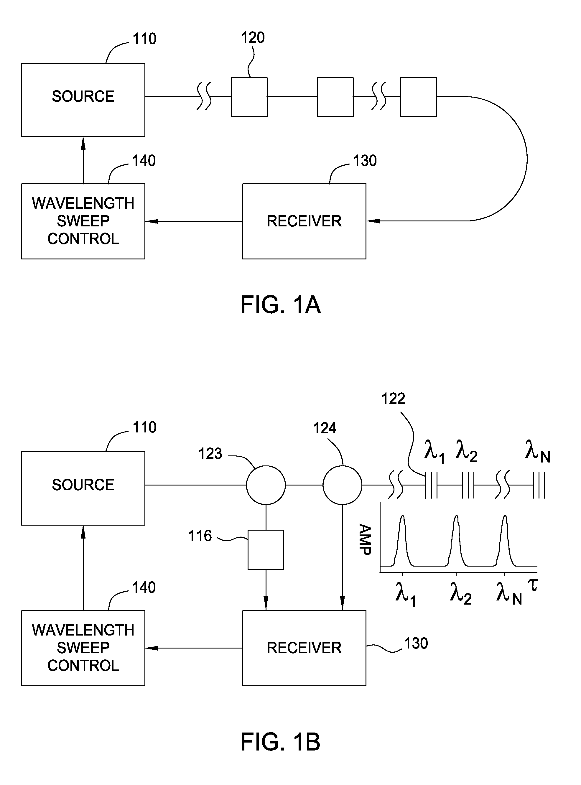
[0034]Wavelength division multiplexing (WDM) systems are typically limited in the number of sensors that can be interrogated on a single fiber. However, using a fast-sweep tunable optical source may increase the number of sensors than can be combined on the fiber, thereby allowing distinguishing among signals from the sensors based on the timing of the received signals and the sweep and, thus, effectively providing for both WDM and time division multiplexing (TDM) on the fiber.

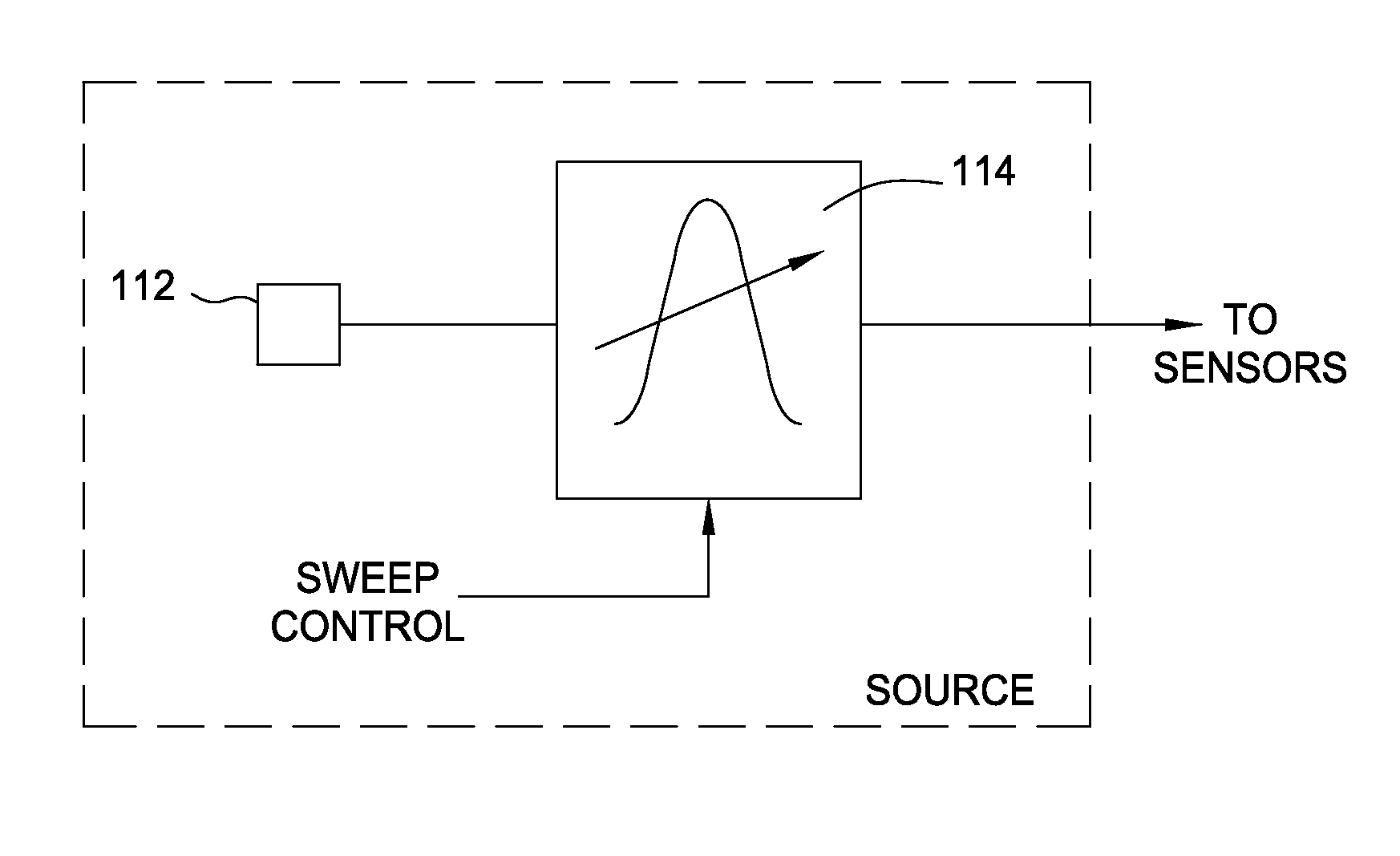
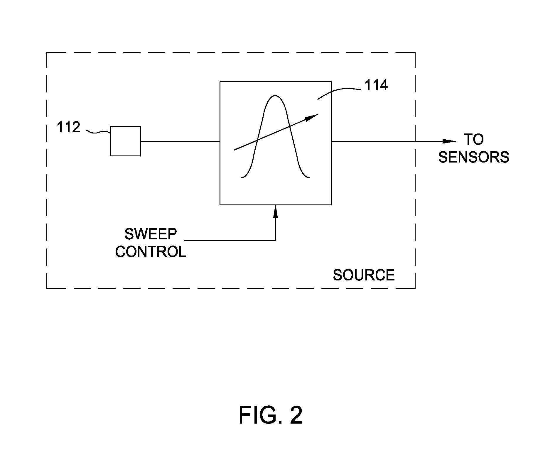
[0035]FIG. 3 illustrates example interrogation of TDMed and effectively WDMed sensors on a single fiber using a fast-swept tunable optical source, in accordance with embodiments of the present invention. As illustrated in FIG. 3, a tunable optical source, such as source 110 (e.g., a tunable laser or amplified spontaneous emission (ASE) source with a tunable filter) may be coupled to an optical waveguide 302 (e.g., an optical fiber) containing multiple optical elements (e.g., fiber Bragg grating (FBG) sensors) ...


PUM

PropertyMeasurementUnit
lengthaaaaaaaaaa
wavelengthsaaaaaaaaaa
lengthaaaaaaaaaa

Abstract

Methods and apparatus for interrogating sets of optical elements having characteristic wavelengths spanning a sweep range while avoiding overlapping reflections from the different sets when performing a wavelength sweep are provided. One example method generally includes introducing a pulse of light, by an optical source, into an optical waveguide to interrogate at least first and second sets of optical elements, wherein the optical elements within each set have different characteristic wavelengths and wherein the first and second sets are separated in time such that a first time window over which light is reflected from the optical elements in the first set and reaches a receiver does not overlap with a second time window over which light is reflected from the optical elements in the second set and reaches the receiver; and processing the reflected light to determine one or more parameters corresponding to the optical elements.

Description

BACKGROUND OF THE INVENTION[0001]1. Field of the Invention[0002]Embodiments of the present invention generally relate to interrogation of optical components and, more particularly, to techniques and apparatus for avoiding overlap of reflections from different arrays of optical elements along the same waveguide when interrogated using wavelength-swept light.[0003]2. Description of the Related Art[0004]Many optical components have a characteristic wavelength that may be found by interrogating the optical component with an optical source capable of producing light at various wavelengths over a fixed range or bandwidth. For example, fiber Bragg gratings (FBGs) (typically formed by photo-induced periodic modulation of the refractive index of an optical waveguide core) are highly reflective to light having wavelengths within a narrow bandwidth centered at a wavelength generally referred to as the Bragg wavelength. Because light having wavelengths outside this narrow bandwidth is passed wi...

Claims


Application Information

Patent Timeline
Patent Type & Authority Applications(United States)
IPC IPC(8): G01N21/47G01M11/02E21B47/00G01M11/00
CPCG01N21/4788G01M11/33G01M11/02G01N2201/08G01N2201/061G01N2201/0696E21B47/0002G01D5/35383G01D5/3539G01D5/353E21B47/002
Inventor TAVERNER, DOMINOGRUNBECK, JOHN J.KIDDY, JASON SCOTT
Owner WEATHERFORD TECH HLDG LLC
Why Eureka
Try Eureka