Correction of calibration errors in an optical instrument

a technology for calibration errors and optical instruments, applied in the field of calibration errors correction, can solve problems such as reducing productivity, requiring error corrections with higher accuracy for error sensitive applications, and large positioning errors, so as to improve productivity, improve accuracy, and eliminate the performance of multiple calibration steps

Active Publication Date: 2011-11-01
TRIMBLE JENA
View PDF13 Cites 5 Cited by
  • Summary
  • Abstract
  • Description
  • Claims
  • Application Information

AI Technical Summary

Benefits of technology

[0008]It is therefore desirable to provide for a calibration error correction device that improves the accuracy of an error correction and that improves productivity by eliminating the performance of multiple calibration steps during use of an optical instrument.
[0009]According to an embodiment a calibration error correction device for an optical instrument comprises a detector of a position of a focusing lens of an optical instrument along a mechanical path of the focusing lens, wherein a line of sight through an image plane of the optical instrument and the focusing lens at a present position defines an actual viewing direction, a memory holding viewing direction error specifying a deviation between a known theoretical viewing direction and the actual viewing direction associated with a plurality of different positions of the focusing lens along the mechanical path, and an indicator to specify at least one value indicative of the actual viewing direction based on the theoretical viewing direction and the viewing direction errors at each of the different positions of the focusing lens along the mechanical path. Accordingly, the calibration error correcting device can provide or a calibration error correction for different focus settings of the optical instrument by using prestored viewing direction errors associated with the different focus settings of the instrument.
[0015]According to another advantageous example a positioning unit is provided to position the focusing lens to focus onto a target and indicate the position of the focusing lens along the mechanical path and, the indicator unit may be adapted to retrieve a viewing direction error associated with the position of the focusing lens based on the position signal indicated by the positioning unit to specify at least one value indicative of the actual viewing direction. Accordingly, the focusing lens may be adjusted to a desired position that is used to obtain an associated viewing direction error and a calibration error at the position can be corrected.
[0016]According to another advantageous example a distance determining unit is provided to determine a distance of a target from the optical instrument and the positioning unit can be adapted to set a position of the focusing lens along the mechanical path to focus onto the target based on the distance, and the indicator unit may be adapted to retrieve a viewing direction error associated with the target distance and to specify at least one value indicative of the actual viewing direction. Thus, the requirement of manual adjustment of the focusing lens can be avoided and the calibration error at the focusing lens position can be directly compensated based on the measured distance to a target.
[0021]According to another advantageous example the calibration unit is adapted to determine a viewing direction error associated with a position of the focusing lens along the mechanical path as a mean between repeated measurements of viewing direction errors at this position of the focusing lens along the mechanical path. Accordingly, measurement errors can be reduced to a minimum.
[0023]According to another advantageous example a unit to measure and compensate for a tilt error can be provided, in order to further improve handling and error correction.

Problems solved by technology

Conceivably, a relatively small error in a measured angle may translate into a potentially large positioning error that may be unacceptable for example in construction applications, especially if the position of an object in a larger distance to the optical instrument is be determined.
While the above outlined calibration of optical instruments works well for many applications, error sensitive applications may require an error correction with higher accuracy.
Moreover, applications requiring a large number of consecutive measurements may require repeated calibration steps for calibrating the optical instrument, thus reducing productivity.

Method used


Image

  • Correction of calibration errors in an optical instrument
  • Correction of calibration errors in an optical instrument
  • Correction of calibration errors in an optical instrument

Examples


Embodiment Construction

[0041]Preferred embodiments of the invention are described with reference to the figures. It is noted that the following description contains examples only and should not be construed as limiting the invention.

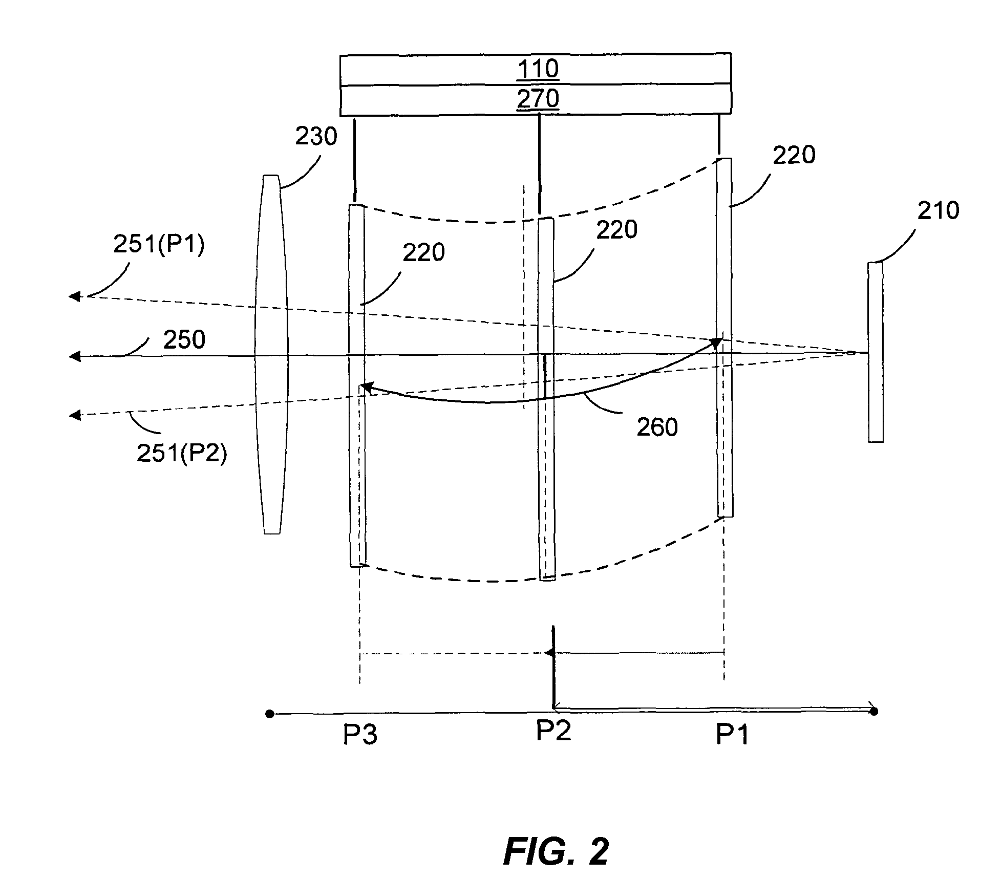
[0042]Embodiments of the invention generally relate to a calibration of optical instruments to improve an accuracy of positional measurements using the optical instrument. Viewing direction errors of a direction measured by the optical instrument are recorded at different positions of a focusing lens along a mechanical path of the focusing lens such as in a telescope of the optical instrument. With the viewing direction errors known at different positions of the focusing lens corresponding to different distances to target objects, positional measurements over a distance range can be made more accurate.

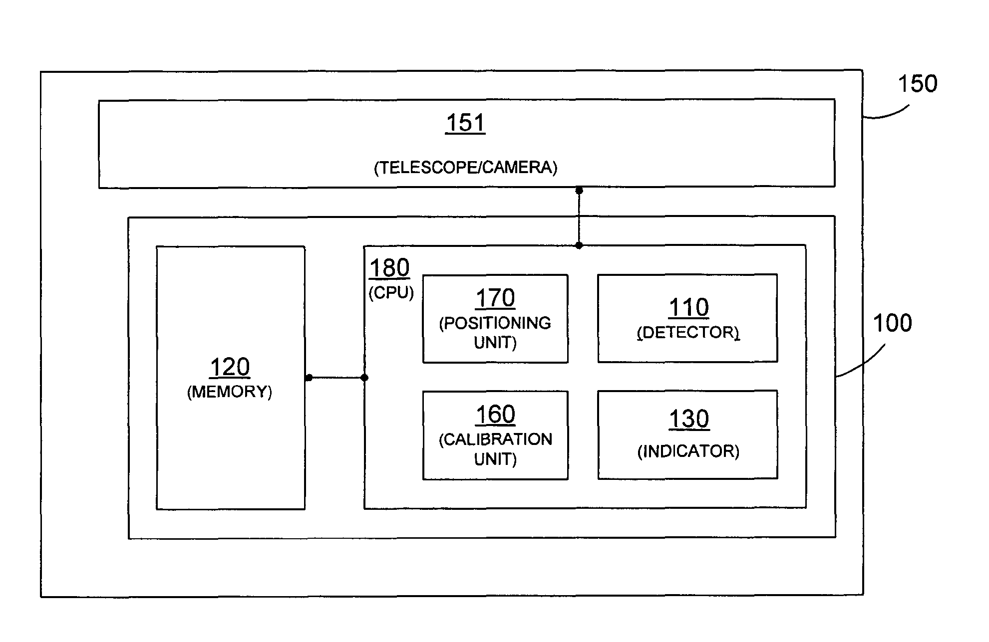
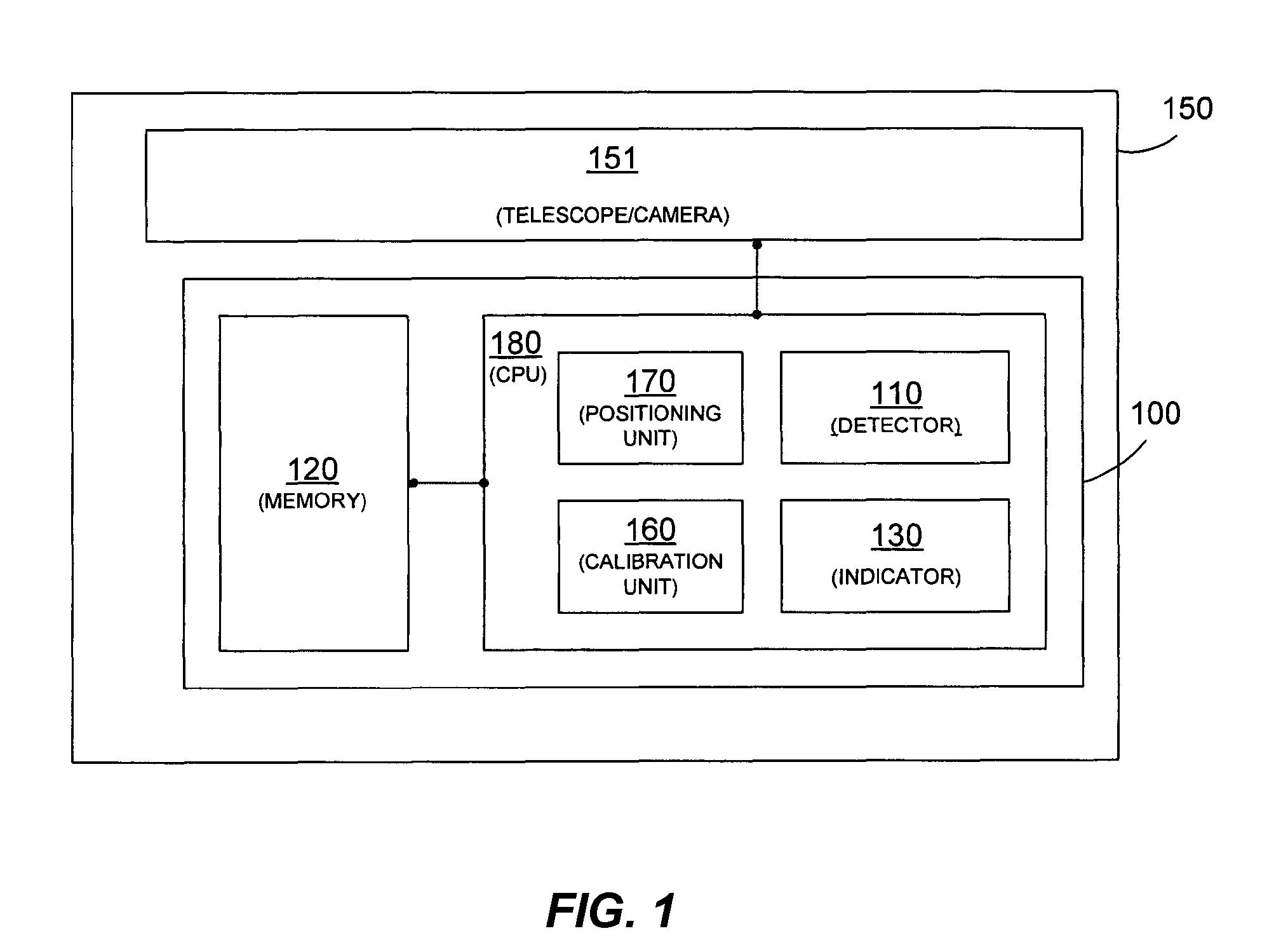
[0043]FIG. 1 illustrates elements of an optical instrument 150 with a calibration error correcting device according to an embodiment of the invention.

[0044]FIG. 1 illustrates a c...


PUM


Abstract

A calibration error correction device for an optical instrument includes a detector operable to detect a position of a focusing lens of an optical instrument along a mechanical path of the focusing lens. A line of sight through an image plane of the optical instrument and the focusing lens at a present position defines an actual viewing direction. The device also includes a memory configured to store viewing direction errors specifying a deviation between a known theoretical viewing direction and the actual viewing direction associated with a plurality of different positions of the focusing lens along the mechanical path and an indicator of at least one value indicative of the actual viewing direction based on the theoretical viewing direction and the viewing direction errors at each of the different positions of the focusing lens along the mechanical path.

Description

CROSS-REFERENCES TO RELATED APPLICATIONS[0001]This application claims priority to and is a continuation of International Patent Application No. PCT / EP2006 / 009026, filed on Sep. 15, 2006, the disclosure of which is hereby incorporated by reference in its entirety for all purposes.BACKGROUND OF THE INVENTION[0002]The present invention relates to the correction of calibration errors, particularly for optical instruments.[0003]Optical instruments generally comprise an arrangement of optical elements such as lenses of a telescope or camera for viewing or to focus onto an object. Further, optical instruments such as a tachymeter or a leveling device are available allowing determining a position of an object relative to a position of the optical instrument. A leveling device generally indicates the relative position of a target object based on a vertical direction only, i.e. the elevation of the target object relative to the position of the leveling device. A tachymeter, on the other hand,...

Claims


Application Information

Patent Timeline
Patent Type & Authority Patents(United States)
IPC IPC(8): H04N17/00G01C25/00G01C5/00G01P21/00
CPCG01C15/00G01C25/00G01M11/0221G02B27/04
Inventor HOFMANN, VOLKMARMAROLD, THOMASMENZEL, MATTHIAS
Owner TRIMBLE JENA
Why Eureka
Try Eureka