Supercharge Your Innovation With Domain-Expert AI Agents!

Heat dissipation device

a heat dissipation device and heat dissipation fin technology, which is applied in indirect heat exchangers, light and heating apparatuses, laminated elements, etc., can solve the problems of inability to efficiently dissipate heat concentrated in the middle of the heat sink, and damage to electronic components

Inactive Publication Date: 2011-11-01
FU ZHUN PRECISION IND SHENZHEN +1
View PDF23 Cites 6 Cited by
  • Summary
  • Abstract
  • Description
  • Claims
  • Application Information

AI Technical Summary

Benefits of technology

This configuration significantly increases airflow to the center of the heat sink, efficiently removing heat concentrated at the motor location, thereby improving the cooling efficiency of electronic components.

Problems solved by technology

If the heat is not efficiently removed, the electronic components may suffer damage.
However, due to blocked access to the motor, only a small portion of the airflow reaches the middle of the heat sink immediately under the motor, such that heat concentrated at the middle of the heat sink cannot be efficiently dissipated.

Method used


Image

  • Heat dissipation device
  • Heat dissipation device
  • Heat dissipation device

Examples


Embodiment Construction

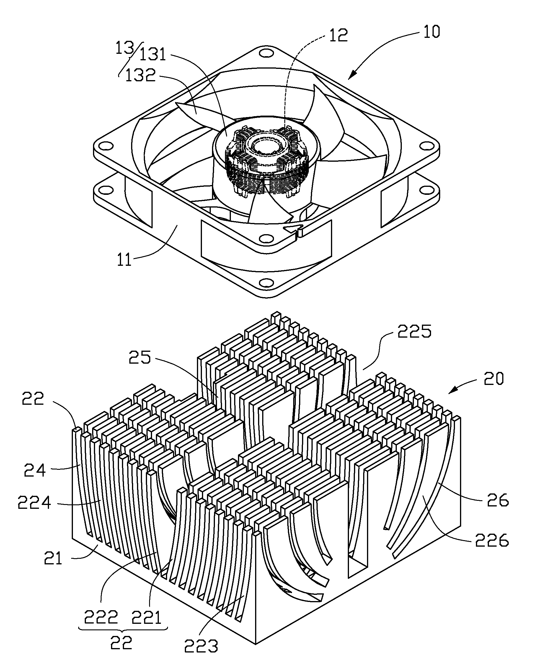
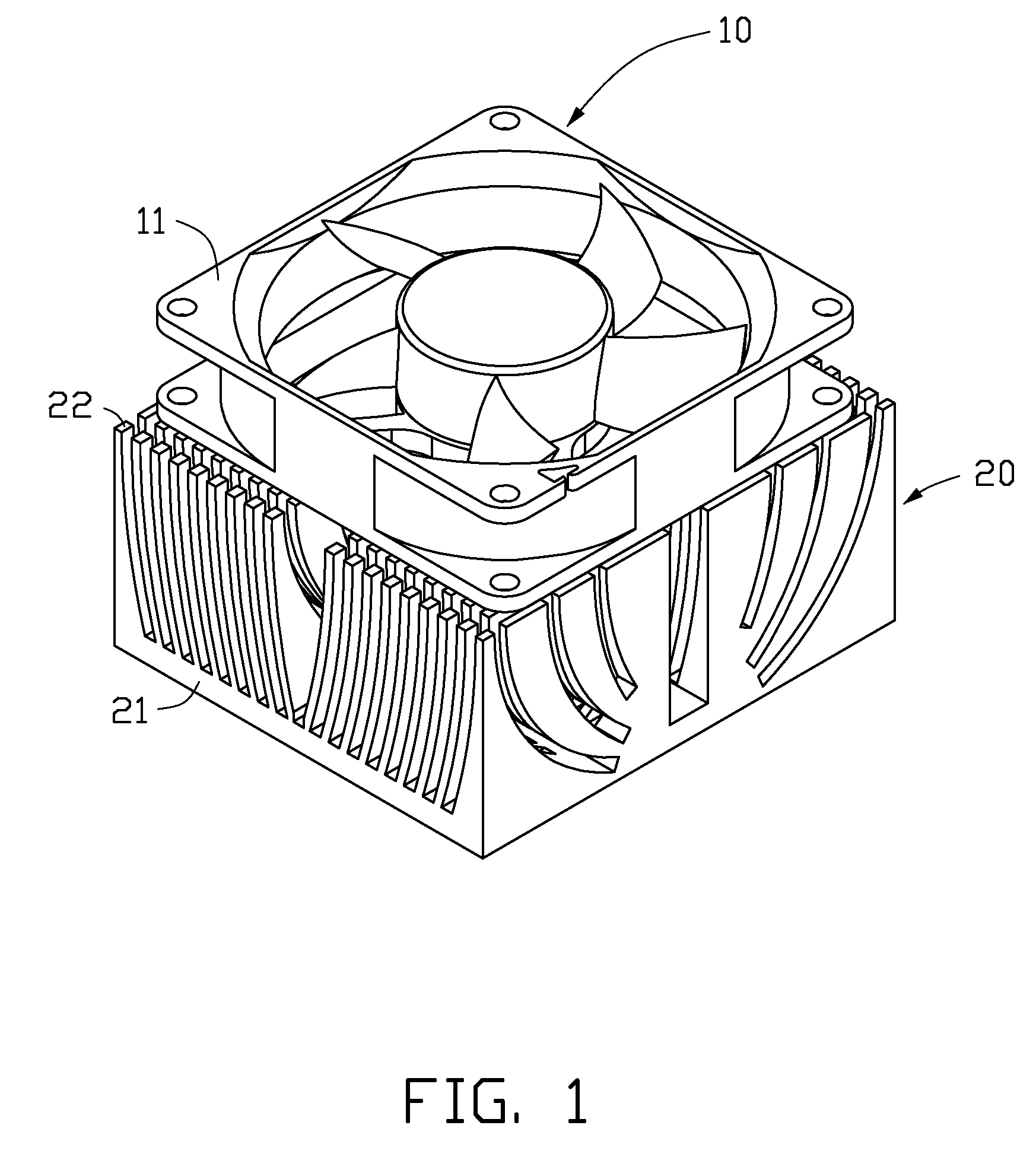
[0011]Referring to FIGS. 1 and 2, a heat dissipation device in accordance with a first embodiment includes a heat sink 20 and a cooling fan 10 arranged on the heat sink 20.

[0012]The cooling fan 10 is an axial fan, and includes a frame 11, a motor-stator 12 mounted in the frame 11, and an impeller 13 mounted around the motor-stator 12. The motor-stator 12 is arranged at the middle of the heat sink 20. The impeller 13 includes a hub 131 covering the motor-stator 12, and a plurality of blades 132 extending radially and outwardly from an outer periphery of the hub 131.

[0013]The heat sink 20 includes a base 21 and a plurality of fins 22 extending upwardly from a top surface of the base 21. The base 21 is rectangular, with a bottom surface thereof thermally contacting with an electronic component (not shown). Each of the fins 22 is arcuate and extends laterally. The fins 22 are divided into two groups: a front group 221 at a front side of the heat sink 20 and a rear group 222 at a rear si...


PUM


Abstract

A heat dissipation device includes a heat sink and a cooling fan arranged thereon. The cooling fan includes a motor-stator and an impeller mounted around the motor-stator. The motor-stator is arranged on a middle of the heat sink. The heat sink includes a base and a plurality of fins extending upwardly from the base. The heat sink defines a plurality of notches incising the fins. The notches are angled towards the middle of the heat sink immediately under the motor-stator of the cooling fan.

Description

BACKGROUND[0001]1. Technical Field[0002]The disclosure relates to heat dissipation, and particularly to a heat dissipation device with improved fin structure.[0003]2. Description of Related Art[0004]It is well known that heat is generated by electronic components such as integrated circuit chips during operation thereof. If the heat is not efficiently removed, the electronic components may suffer damage. Thus, heat dissipation devices are often used to cool the electronic components.[0005]A typical heat dissipation device includes a heat sink and a cooling fan arranged on the heat sink. Electronic components are usually attached to a center of the heat sink, the location at which heat generated by the electronic component is primarily concentrated. The cooling fan includes a motor at a center thereof, and an impeller mounted around the motor. During operation of the cooling fan, the motor drives the impeller to rotate and generate airflow towards the heat sink. However, due to block...

Claims


Application Information

Patent Timeline
Patent Type & Authority Patents(United States)
IPC IPC(8): H05K7/20
CPCH01L23/467F28F3/02H01L2924/0002H01L2924/00
Inventor YU, YE-FEIXU, SHU-YUANZHA, XIN-XIANGYANG, LINDING, JUNKUO, JER-HAUR
Owner FU ZHUN PRECISION IND SHENZHEN
Features
  • R&D
  • Intellectual Property
  • Life Sciences
  • Materials
  • Tech Scout
  • Unparalleled Data Quality
  • Higher Quality Content
  • 60% Fewer Hallucinations
Learn More