Optical module

a technology of optical communication cable and optical element, applied in the field of optical communication cable module, can solve the problems of being susceptible to heat, unable to meet the requirements of low-height modules, and difficulty in achieving low-height modules, etc., to achieve satisfactory space-saving circuit design, maintain optical coupling efficiency, and improve the degree of freedom of wiring (wire) connecting the optical element and the ic

Inactive Publication Date: 2011-11-08
ORMON CORP
View PDF33 Cites 4 Cited by
  • Summary
  • Abstract
  • Description
  • Claims
  • Application Information

AI Technical Summary

Benefits of technology

[0024]As a countermeasure therefore, consideration is made in fixing both ends of the optical waveguide that are projected. However, when attempting to ensure a stable adhering area of the optical waveguide, in view of the mounting precision of the optical element to couple and the mounting precision of the optical waveguide, to fix both ends of the optical waveguide, the interval of the supporting part at both ends is widened and the width of the waveguide to be mounted thereon also needs to be widened, whereby the twistability of the film-type optical waveguide significantly lowers.
[0026]In the above described configuration, the region of the distal end of the optical waveguide, that is, the first region is supported, and thus deformation of the end of the optical waveguide caused by change in the usage environment temperature of the optical module, heat generation of peripheral components, external force of vibration / drop, and the like is suppressed, compared to the conventional configuration. Therefore, the distance and the position relationship between the entrance / exit port of the optical signal in the end of the optical waveguide and the optical element can be maintained constant, and the optical coupling efficiency can be maintained constant.
[0027]Since only the end on one side of the optical waveguide can be supported, the degree of freedom of wiring (wire) connecting the optical element and the IC can be increased, and thus the degree of freedom of the mounting position of electronic components such as optical element and IC increases without causing degradation of signal noise, and a satisfactory space-saving circuit design can be realized.
[0028]Furthermore, the interval of the optical waveguide can be narrowed regardless of whether or not the supporting part is included even when using a plurality of optical waveguides as in bi-directional communication, and the bi-directional communication function can be compactly realized.
[0029]Thus, miniaturization of the optical can be realized and fluctuation of the optical coupling efficiency can be suppressed without complicating the structure of the optical module, that is, with a simple configuration of supporting at least one part of the distal end of the optical waveguide.

Problems solved by technology

The method of fixing the optical waveguide with the holding member such as ferrule used as a connecting technique of a rigid optical waveguide is methodically difficult when using a very flexible optical waveguide due to its flexibility.
Consideration is made in reinforcing the flexible optical waveguide with a rigid member, but a problem arises in the optical system, in which a 45 degrees mirror and the like are arranged, in that the outer shape of the distal end becomes large thereby shielding the optical path, and realization of a low height module becomes difficult particularly for the commercial-off-the-shelf equipments such as information terminal.
In particular, polymer waveguide is often used when using the film-type optical waveguide having high flexibility, in which case the coefficient of thermal expansion is large and the coefficient is constituted by the core and the clad having different flexibilities, and thus has a property of being susceptible to heat.
In the methods described in patent documents 2 and 3, a height direction becomes large and miniaturization becomes difficult since the light receiving / emitting element and the optical waveguide are directly joined with adhesive.

Method used


Image

  • Optical module
  • Optical module
  • Optical module

Examples


Embodiment Construction

[0076]One embodiment of the present invention will be described below using FIG. 1 to FIG. 29.

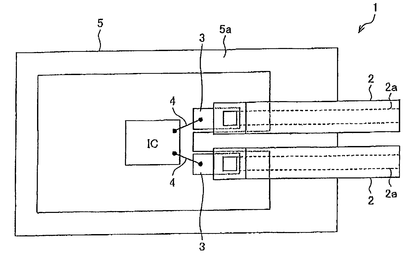
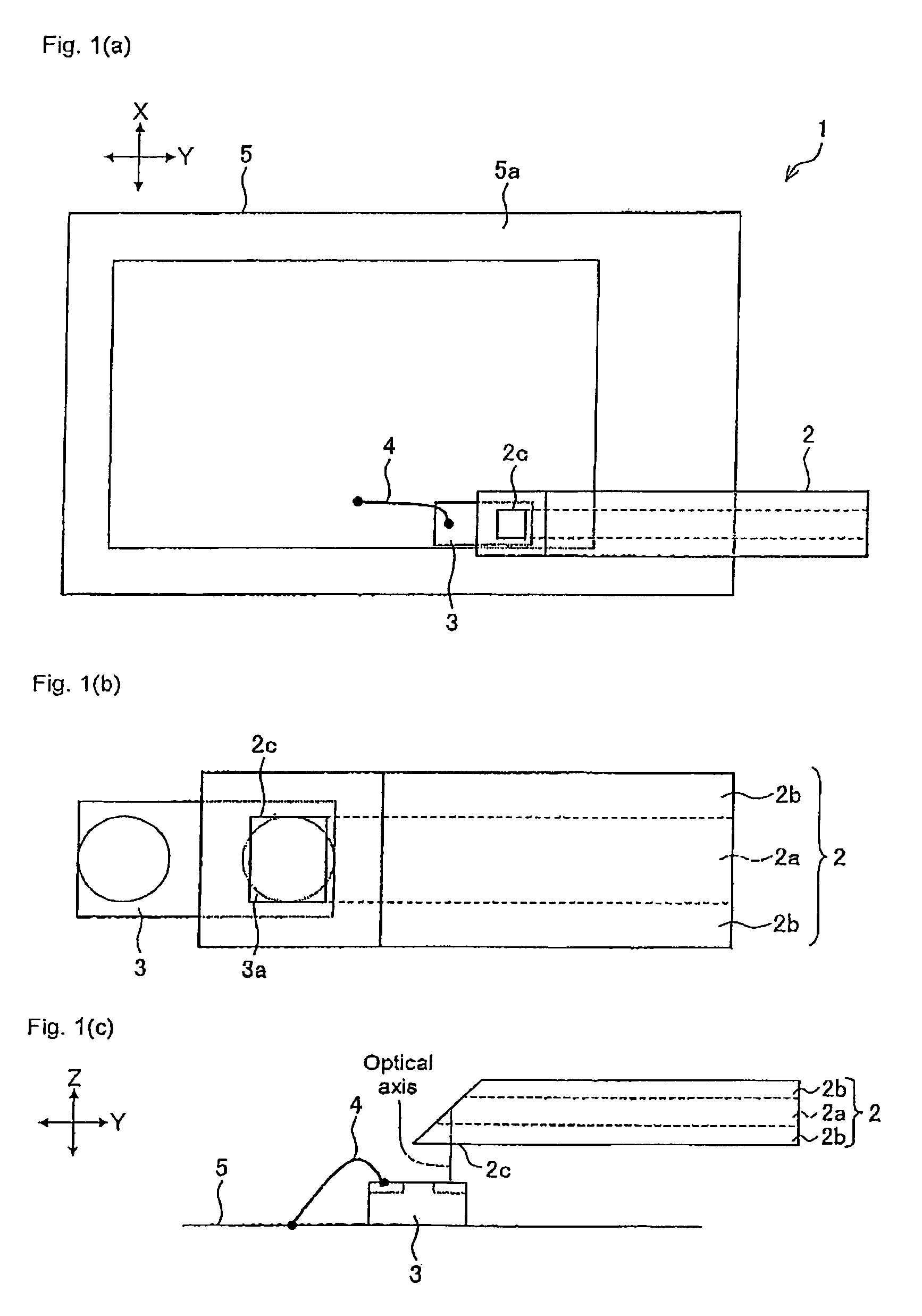
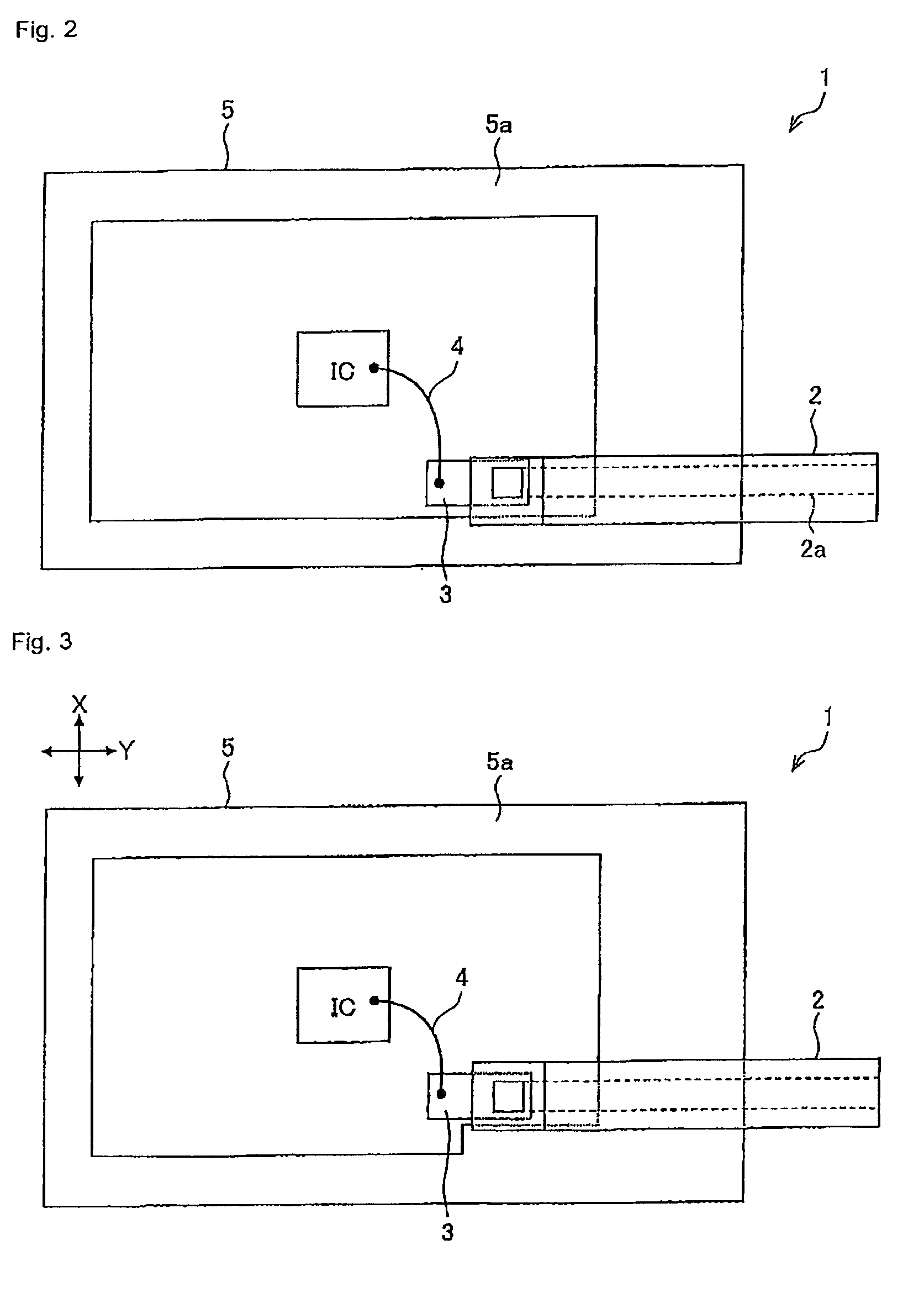
[0077]FIG. 1 (a) is a plan view showing a schematic configuration of an optical module 1 according to the present embodiment, FIG. 1 (b) is an enlarged view of an end of an optical waveguide 2, and FIG. 1 (c) is a side view showing a schematic configuration of the optical module 1.

[0078]The optical module 1 includes the optical waveguide 2, a light receiving / emitting element (optical element) 3, a bonding wire 4, and a package 5.

[0079]The optical waveguide 2 is configured by a core part 2a having a large index of refraction and a clad part 2b having a small index of refraction arranged contacting the periphery of the core part 2a, and is made to propagate an optical signal entered to the core part 2a while repeating total reflection at the boundary of the core part 2a and the clad part 2b. The optical waveguide 2 has flexibility since the core part 2a and the clad part 2b are made of polyme...


PUM


Abstract

An optical module (1) including a light receiving / emitting element (3) for transmitting or receiving an optical signal, an optical waveguide (2) having a core part made of a material with translucency and a clad part made of a material having an index of refraction different from an index of refraction of the core part for optically coupling with the light receiving / emitting element (3) and transmitting the optical signal, and a package (5) for accommodating at least one end including an entrance / exit port (2c) of the optical signal in the optical waveguide (2) and the light receiving / emitting element (3); wherein a surface on a side facing a bottom plate mounted with the light receiving / emitting element (3) in the package (5) at the end of the optical waveguide (2) accommodated in the package (5) is configured by a first region including a portion projected into a space inside the package (5), and a second region different from the first region; and the package (5) includes a supporting part (5a) for supporting one part of at least one side of the surface forming the first region in the first region, and supporting one part of at least two sides of the surface forming the second region in the second region.

Description

TECHNICAL FIELD[0001]The present invention relates to an optical communication cable module, and in particular, to a package in an optical cable having flexibility.BACKGROUND ART[0002]In recent years, in particular, there has been a demand for realizing a flexible optical wiring to be mounted (similar to electrical wiring) on bendable displays and more compact and thin commercial-off-the-shelf equipments with an optical waveguide.[0003]In applications such as portable terminal, in particular, there has been desired a new wiring capable of forming patterns such as the conventional FPC (printed circuit board), and having flexibility (particularly twistability) and noise-resistance property such as coaxial cable, and in that sense, there has been desired a new wiring which uses a bendable, twistable, and flexible film-type optical waveguide.[0004]The optical waveguide is formed by a core having a large index of refraction, and a clad having a small index of refraction arranged contacti...

Claims


Application Information

Patent Timeline
Patent Type & Authority Patents(United States)
IPC IPC(8): G02B6/36G02B6/42
CPCG02B6/1221G02B6/4201G02B6/4219G02B6/4212G02B6/4214H01L2224/48091H01L2924/3025H01L2924/00014H01L2924/00G02B6/4242G02B6/122G02B6/42
Inventor SAMESHIMA, HIROSHIKOIKE, TAKAYOSHIYASUDA, NARUHOSOKAWA, HAYAMINOZAWA, HIROTO
Owner ORMON CORP
Why Eureka
Try Eureka