Seal ring

A sealing ring and shell technology, which is applied to the sealing of engines, engine components, mechanical equipment, etc., can solve the problems of reduced sealing performance, unstable sealing performance, and changes in contact areas, so as to reduce sliding resistance and stabilize sealing performance The effect of reducing and reducing the torque

Active Publication Date: 2020-02-07
NOK CORP
View PDF10 Cites 5 Cited by
  • Summary
  • Abstract
  • Description
  • Claims
  • Application Information

AI Technical Summary

Problems solved by technology

Therefore, depending on the usage environment, the contact area between the seal ring 300 and the side wall surface of the annular groove 510 may become too small, which may result in a decrease in sealing performance.
In addition, there are problems such as changes in the contact area depending on the use environment, making the sealing performance unstable.

Method used


Image

  • Seal ring
  • Seal ring
  • Seal ring

Examples


Embodiment Construction

[0030] Hereinafter, modes for implementing the present invention will be described in detail based on examples with reference to the drawings. However, unless otherwise specified, the dimensions, materials, shapes and relative positions of the components described in this embodiment are not intended to limit the scope of the present invention thereto.

[0031] (Example)

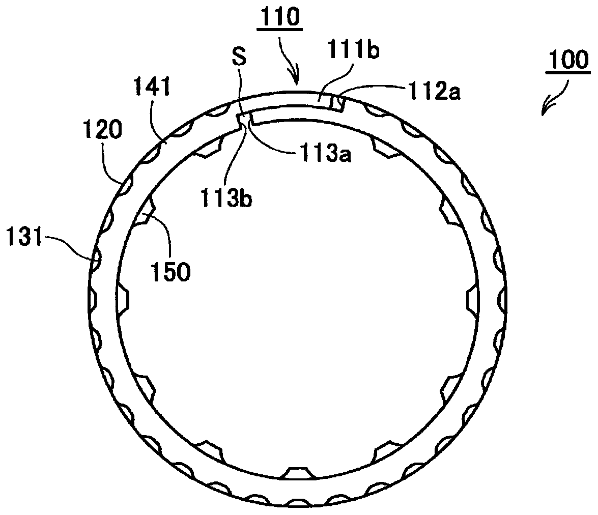
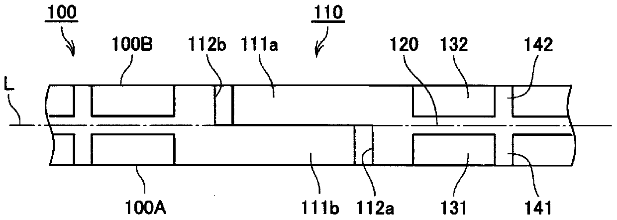
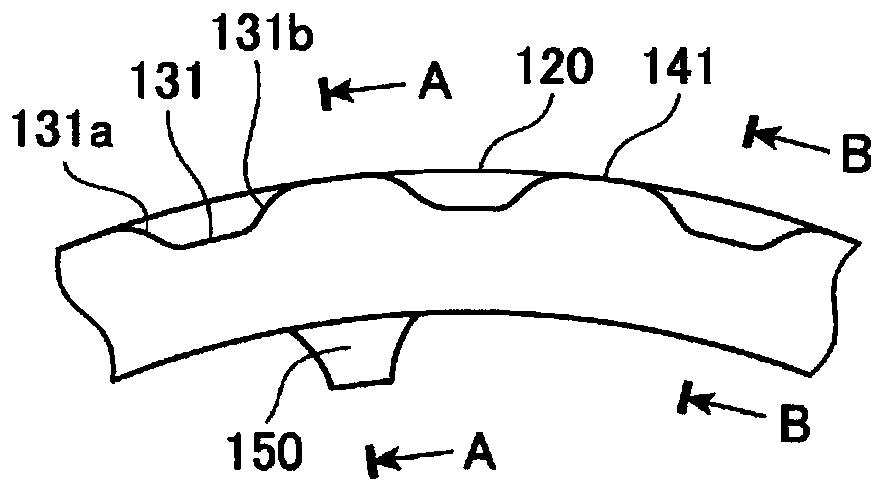
[0032] refer to Figure 1 to Figure 6 The seal ring according to the embodiment of the present invention will be described. figure 1 It is a side view of the sealing ring involved in the embodiment of the present invention. figure 2 It is a part of the figure seen from the outer peripheral surface side of the seal ring according to the embodiment of the present invention, and is a view showing the vicinity of the joint portion provided on the seal ring. image 3 It is a partial enlarged view of the side view of the sealing ring involved in the embodiment of the present invention. Figure 4 ~ Figure 6 It...


PUM


Abstract

The objective of the present invention is to provide a seal ring with which sealing performance is stabilized while rotational torque is reduced. The seal ring is characterized in that a plurality offirst dynamic pressure generating grooves (131) which are provided extending from a position displaced toward a side surface (100A) on one side, from the center of the width in an axial direction, tothe side surface (100A) on the one side and which generate dynamic pressure as a result of relative rotation between a housing and the seal ring (100), and a plurality of second dynamic pressure generating grooves (132) which are provided extending from a position displaced toward a side surface (100B) on the other side, from the center of the width in the axial direction, to the side surface (100B) on the other side and which generate dynamic pressure as a result of relative rotation between the housing and the seal ring (100) are provided spaced apart in the circumferential direction on an outer circumferential surface side of the seal ring (100).

Description

technical field [0001] The invention relates to a sealing ring for sealing the annular gap between the shaft and the shaft hole of the casing. Background technique [0002] In Automatic Transmission (AT) or Continuously Variable Transmission (CVT) for automobiles, a seal ring is provided to seal the annular gap between the relatively rotating shaft and the housing in order to maintain oil pressure. In recent years, low fuel consumption has been promoted as a countermeasure against environmental problems, and there has been an increasing demand for torque reduction in the above-mentioned seals. Hitherto, countermeasures have been taken to reduce the contact area of ​​the sliding portion between the side surface of the annular groove on which the seal ring is mounted and the seal ring. refer to Figure 10 A seal ring according to such a conventional example will be described. [0003] Figure 10 It is a schematic cross-sectional view showing the state of use of the seal ring...

Claims


Application Information

Patent Timeline
Patent Type & Authority Applications(China)
IPC IPC(8): F16J15/48F16J15/18
CPCF16J15/3272F16J15/3244F16J15/441F16J15/26F16J15/48F16J15/18F16J15/3284
Inventor 吉田勇介渡部浩二
Owner NOK CORP
Why Eureka
Try Eureka