Mold having a coaxial cooling and heating coil structure

a technology of coaxial cooling and heating coils, which is applied in the direction of indirect heat exchangers, food shaping, light and heating apparatus, etc., can solve the problems of shortening the mold structure of conventional molds, affecting the production yield of injection molding, and increasing the energy needed for preheating, so as to reduce the time required for cooling and enhance the preheating efficiency of molds

Active Publication Date: 2011-11-08
CHUNG YUAN CHRISTIAN UNIVERSITY
View PDF8 Cites 10 Cited by
  • Summary
  • Abstract
  • Description
  • Claims
  • Application Information

AI Technical Summary

Benefits of technology

In view of the disadvantages of prior art, the object of the present invention is to provide a coaxial cooling / heating coil structure and a mold configured with the same, capable of enhancing the preheating efficiency of the mold while reducing the time required for cooling the mold as the coaxial cooling / heating coil structure is configured with a heat-conducting coil being coaxially disposed inside its cooling channel.

Problems solved by technology

Nevertheless, the aforesaid conventional mold structure is shorted in the sizes of its male die and female die as they can be very big and bulky.
As a larger die will required a longer time for preheating the same to a specific temperature, the production time for an injection molding process using the mold to produce a product is prolonged and consequently the production yield of the injection molding is adversely affected.
Not to mention that the lager a die is, the more energy it will need for the preheating which not only is not energy efficient, but also can be very costly.
Moreover, as there is cooling water kept circulating inside the cooling pipe even at the time when the electric heating coil is activated for preheating the male die or female die, the male die or female die is being cooling down as it is being heated which not only might prevent the same from being heated to the specific temperature, but also can waste a lot of energy.
Nevertheless, although the aforesaid external heater is able to achieve the expected preheating effect, it can be very time-consuming and difficult to apply that it is only suitable for large-size forging machines or injection molds, and is not adapted for molds of precision injection molding.
However, as the cooling water is flowing inside the heating coil, the cooling water is not able to cool down the corresponding mold effectively and thus the heat dissipating efficiency of the mold is poor.
If a better cooling effect is required, it is required to increase the inner diameter of the heating coil for increasing the flow of the cooling water, but at the cost of larger and heavier heating coil.
However, those prior-art preheating devices are only aimed for the improvement in preheating efficiency.

Method used


Image

  • Mold having a coaxial cooling and heating coil structure
  • Mold having a coaxial cooling and heating coil structure
  • Mold having a coaxial cooling and heating coil structure

Examples


Embodiment Construction

For your esteemed members of reviewing committee to further understand and recognize the fulfilled functions and structural characteristics of the invention, several exemplary embodiments cooperating with detailed description are presented as the follows.

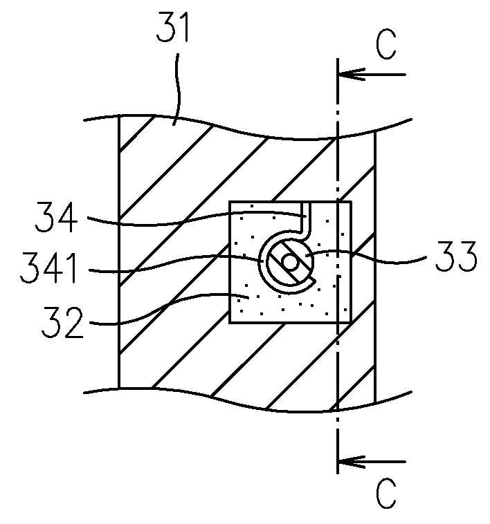
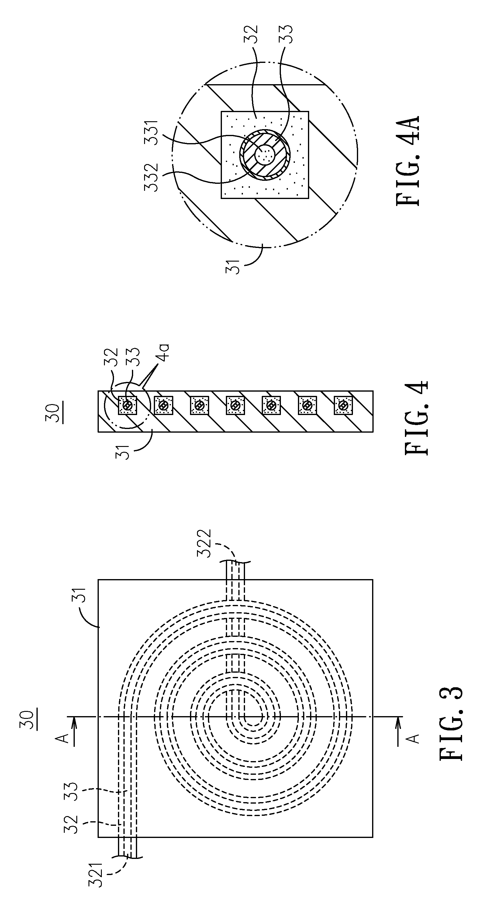
Please refer to FIG. 3 to FIG. 4A, which show a coaxial cooling / heating coil structure according to a first embodiment of the invention. The coaxial cooling / heating coil structure 30 in this embodiment comprises: a frame 31; a cooling channel 32, arranged at the frame 31 and configured with an inlet 321, provided for a cooling water to flow therein, and an outlet 322, provided for discharging the cooling water therefrom; and a heat-conducting coil 33, disposed inside the cooling channel 32 and capable of being activated for heating by an high-frequency induction manner. As shown in FIG. 4A, the heat-conducting coil 331 is a hollow tube with an internal cooling channel 331 formed therein. The internal cooling channel 331 is configure...


PUM

PropertyMeasurementUnit
shapeaaaaaaaaaa
heightsaaaaaaaaaa
heat-aaaaaaaaaa

Abstract

The present invention relates to a coaxial cooling / heating coil structure and a mold configured with the same, in which the coaxial cooling / heating coil is comprised of: a frame, configured with a cooling channel having an inlet, provided for a cooling water to flow therein, and an outlet, provided for discharging the cooling water therefrom; and a heat-conducting coil, disposed inside the cooling channel. The coaxial cooling / heating structure is fitted to a mold to be used for enhancing the preheating efficiency of the mold while improving the time required for cooling the mold.

Description

FIELD OF THE INVENTIONThe present invention relates to a coaxial cooling / heating coil structure and a mold configured with the same, and more particularly, to a high-frequency heating coil structure having a heat-conducting coil coaxially disposed inside its cooling channel.BACKGROUND OF THE INVENTIONIn the operation of injection molding process, it is common to preheat the female die and male die to a specific temperature before the two dies are integrated for injection since the preheated mold can prevent the melted plastic from cooling down too rapidly and becoming somewhat “sticky” and thus ensure the melted plastic that is being injected into the same through its sprue gate, to flow smoothly therein and arrive at the mold cavity for molding.It is noted that the conventional preheating structures for injection molds, which can be electric heaters or high-frequency heater, are fixed heaters being fitted inside either the female die or the male die of the injection molds. As a con...

Claims


Application Information

Patent Timeline
Patent Type & Authority Patents(United States)
IPC IPC(8): B29C45/73
CPCB29C33/04B29C33/06B29C35/0805B29C45/73H05B6/42B29C35/041B29C2035/0811B29C2035/0816B29C2035/1616B29C2045/7368B29C2045/7393
Inventor CHEN, SHIA-CHUNGCHANG, JEN-AN
Owner CHUNG YUAN CHRISTIAN UNIVERSITY
Why Eureka
Try Eureka