Supercharge Your Innovation With Domain-Expert AI Agents!

Multichannel amplifier

a multi-channel amplifier and amplifier technology, applied in the direction of stereophonic arrangments, gain control, stereophonic circuit arrangements, etc., can solve the problems of deteriorating sound quality and increasing cost, and achieve the effect of high sound output quality

Inactive Publication Date: 2011-11-08
ONKYO KK
View PDF21 Cites 2 Cited by
  • Summary
  • Abstract
  • Description
  • Claims
  • Application Information

AI Technical Summary

Benefits of technology

The solution ensures higher quality sound output from the front speaker without interference from the headphone audio path, achieved by using switch ICs instead of relays and buffer circuits to manage signal paths, resulting in improved sound quality and cost-effectiveness.

Problems solved by technology

There is, consequently, a problem such that the input impedance of the front channel amplifying unit 4a drops and a wire to the headphone amplifying unit 4c becomes an inductor component, thereby deteriorating the sound quality.
However, the relays are expensive, so that a problem of increase in cost occurs.

Method used


Image

  • Multichannel amplifier
  • Multichannel amplifier
  • Multichannel amplifier

Examples


Embodiment Construction

[0020]A multichannel amplifier according to preferred embodiments of the present invention will be described hereinbelow, but the invention is not limited to the embodiments. The same reference numerals are given to the same or corresponding parts in the diagrams and their repetitive description will not be given.

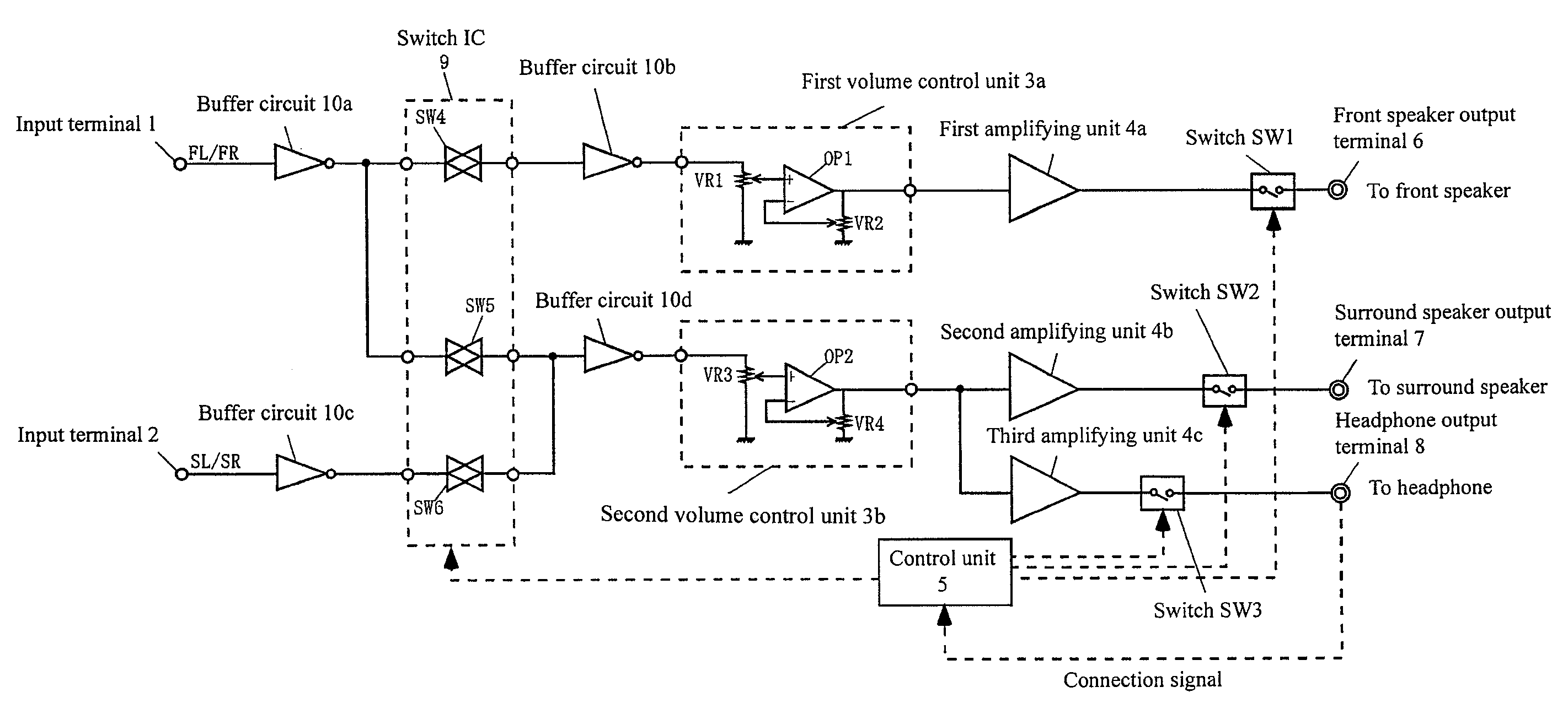
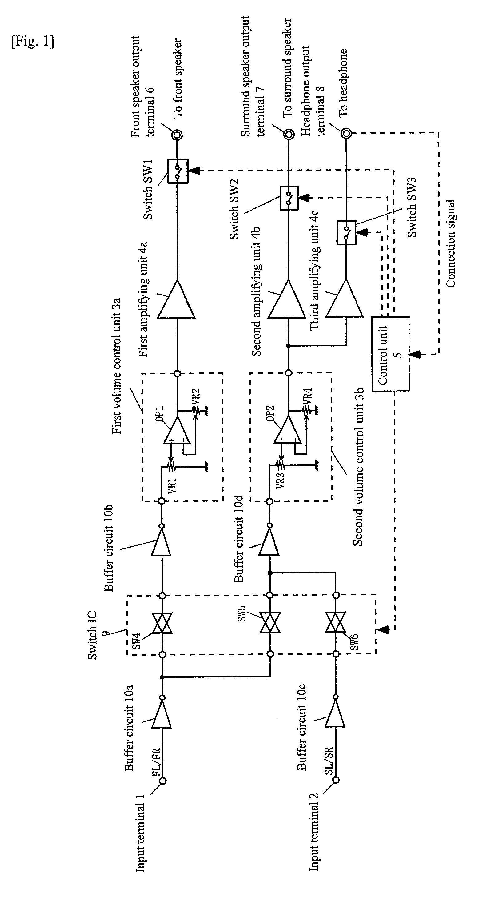
[0021]First, referring to FIG. 1, a schematic configuration of a multichannel amplifier of the present invention will be described. FIG. 1 is a circuit diagram showing a multichannel amplifier according to a preferred embodiment of the invention.

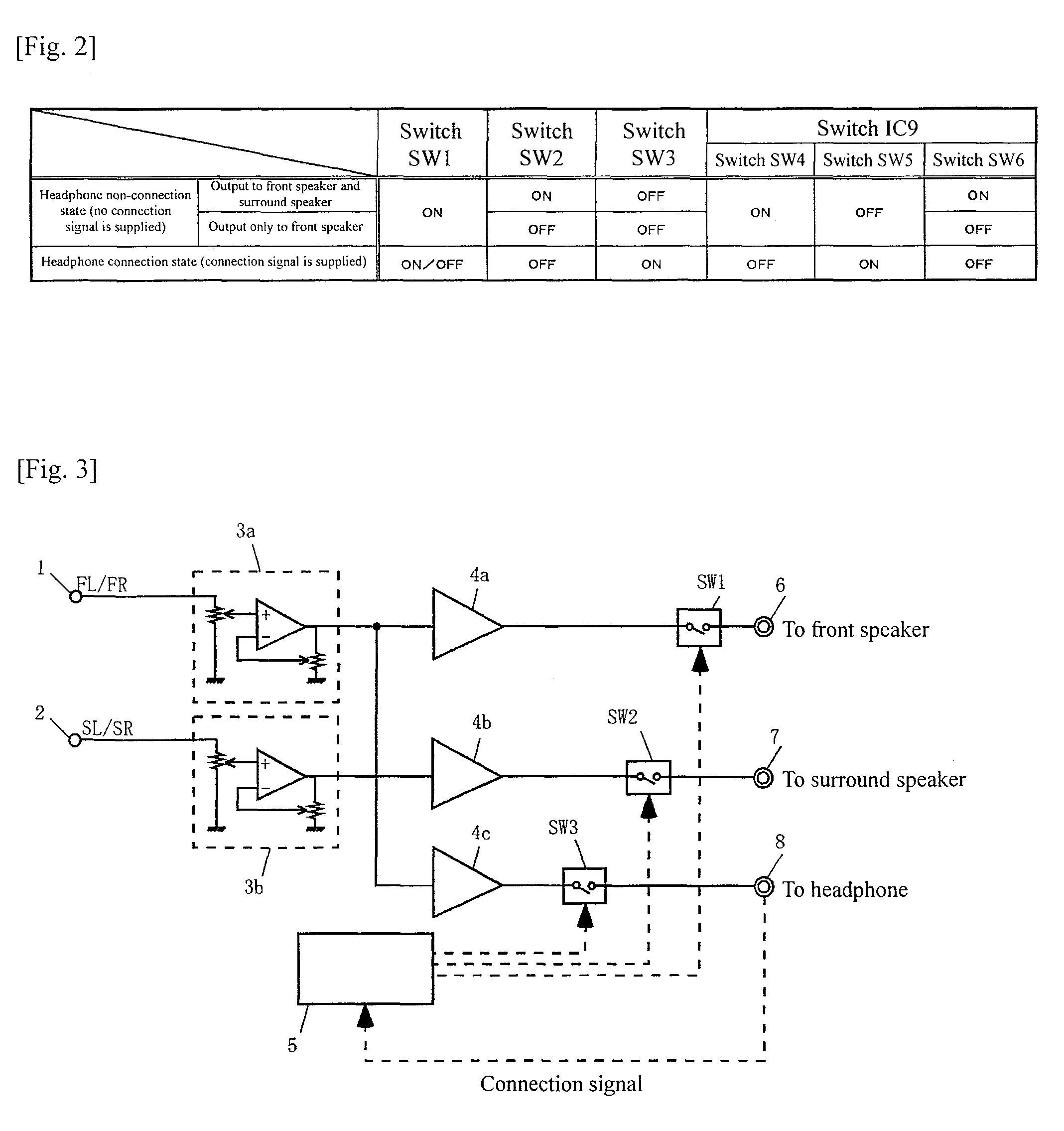
[0022]A multichannel amplifier has a first input terminal 1, a second input terminal 2, a first volume control unit 3a, a second volume control unit 3b, a first amplifying unit 4a, a second amplifying unit 4b, a third amplifying unit 4c, a control unit 5, a front speaker output terminal 6 to which a front speaker (not shown) is connected, a surround speaker output terminal 7 to which a surround speaker (not shown) is connected, a he...


PUM


Abstract

In a multichannel amplifier according to the present invention, in a case where a headphone is not connected to a headphone output terminal, a switch IC and first to third switches are on / off controlled by a control unit so that an audio signal path for outputting a front channel signal FL / FR to a front speaker and extending from a first input terminal 1 to a front speaker output terminal 6 via a buffer circuit 10a, a switch IC 9, a first volume control unit 3a, a buffer circuit 10b, and a first amplifying unit 4a is not electrically connected to another audio signal path.

Description

BACKGROUND OF THE INVENTION[0001]1. Field of the Invention[0002]The present invention relates to a multichannel amplifier having an amplifying unit for a headphone.[0003]2. Description of the Related Art[0004]A conventional multichannel amplifier will be described. FIG. 3 is a circuit diagram showing a schematic configuration of the conventional multichannel amplifier. The conventional multichannel amplifier has a volume control unit 3a for a front channel, a volume control unit 3b for a surround channel, an amplifying unit 4a for a front channel, an amplifying unit 4b for a surround channel, an amplifying unit 4c for a headphone, a control unit 5, an output terminal 6 for a front speaker, an output terminal 7 for a surround speaker, an output terminal 8 for a headphone, and switches SW1 to SW3.[0005]To the front channel volume control unit 3a, a front channel signal FL / FR as an analog audio signal is inputted via an input terminal 1. The front channel volume control unit 3a control...

Claims


Application Information

Patent Timeline
Patent Type & Authority Patents(United States)
IPC IPC(8): H04R5/02
CPCH04R5/04H04R5/033H04R2420/05H04R2430/01
Inventor OKAMURA, TOSHIFUMIETOH, NORIO
Owner ONKYO KK
Features
  • R&D
  • Intellectual Property
  • Life Sciences
  • Materials
  • Tech Scout
  • Unparalleled Data Quality
  • Higher Quality Content
  • 60% Fewer Hallucinations
Learn More