Landscape edging clip

a technology for landscapes and edgings, applied in the field of landscape edgings, can solve the problems of failure of a connection, increased labor costs for properly installing, and additional hardware and labor intensive installation, and achieve the effect of quick installation, quick and easy completion, and increased force applied

Active Publication Date: 2011-11-15
PERMALOC CORP
View PDF9 Cites 9 Cited by
  • Summary
  • Abstract
  • Description
  • Claims
  • Application Information

AI Technical Summary

Benefits of technology

[0007]The objects and purposes of this invention are met by providing a U-shaped clip that can be quickly installed by attaching the clip over the top edge of the vertical wall of the restraint. This action is quick and easily accomplished by hand, requiring no tools or forceful effort. The clip forms a strong connection through the use of a series of pointed, opposing, hardened steel barbs that bite into the softer edging material to create a mechanical lock. Further, the barbs are angled so as to increase the force applied to the edging material as the parts are drawn apart in opposite directions.

Problems solved by technology

The point of connection between adjacent sections is, mechanically, the weakest point in the system and generates an increased labor cost to properly install.
Although many edging systems currently incorporate some type of connection system, these connections are limited in that they are either permanently affixed to the end of the edging lengths, being rendered useless when edging sections must be cut to a shorter length, or are secondary systems that require additional hardware and are labor intensive to install.
As is well known, the landscape is a dynamic constantly moving environment that will quickly cause failure of a connection based upon friction as the sole means of binding.

Method used


Image

  • Landscape edging clip
  • Landscape edging clip
  • Landscape edging clip

Examples


Embodiment Construction

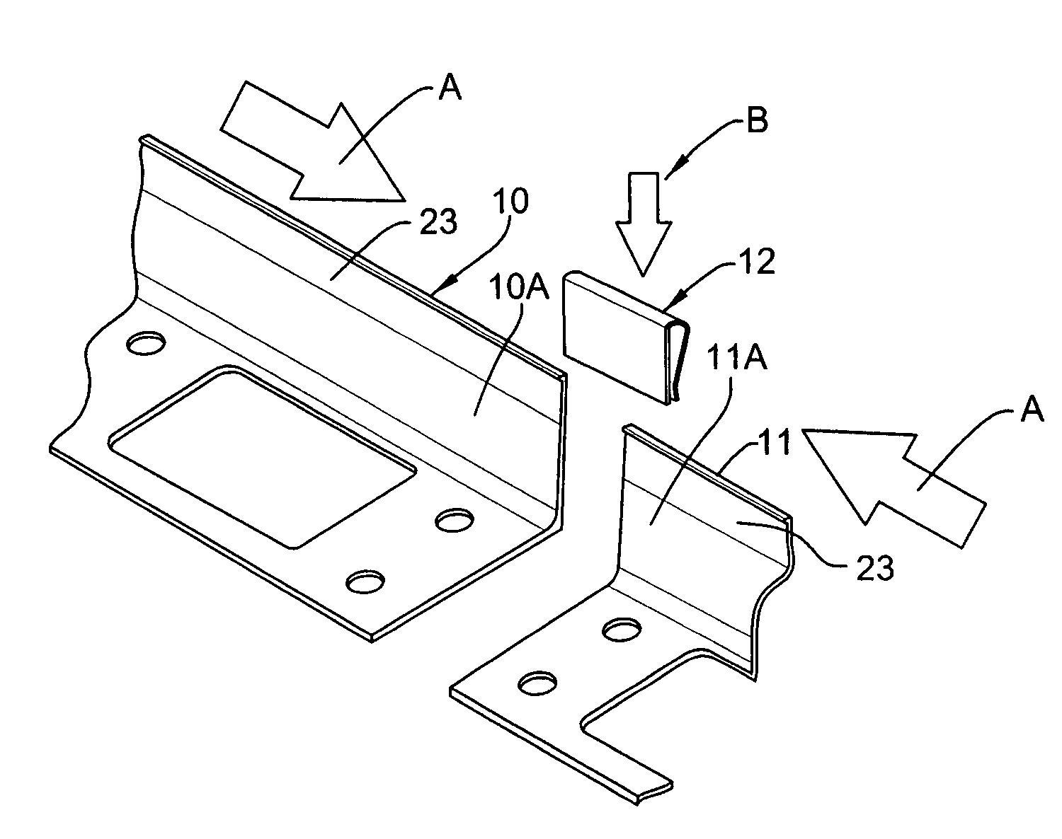
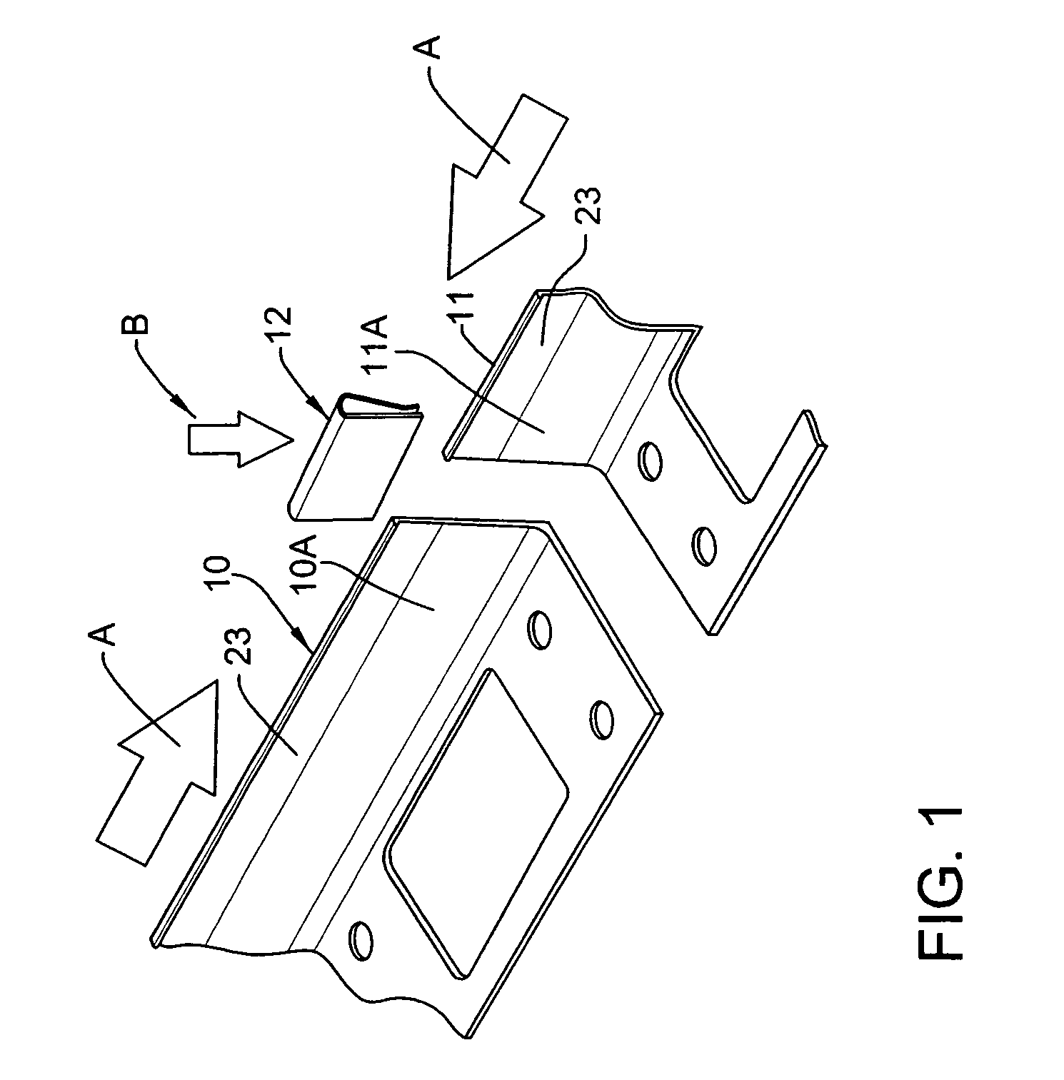
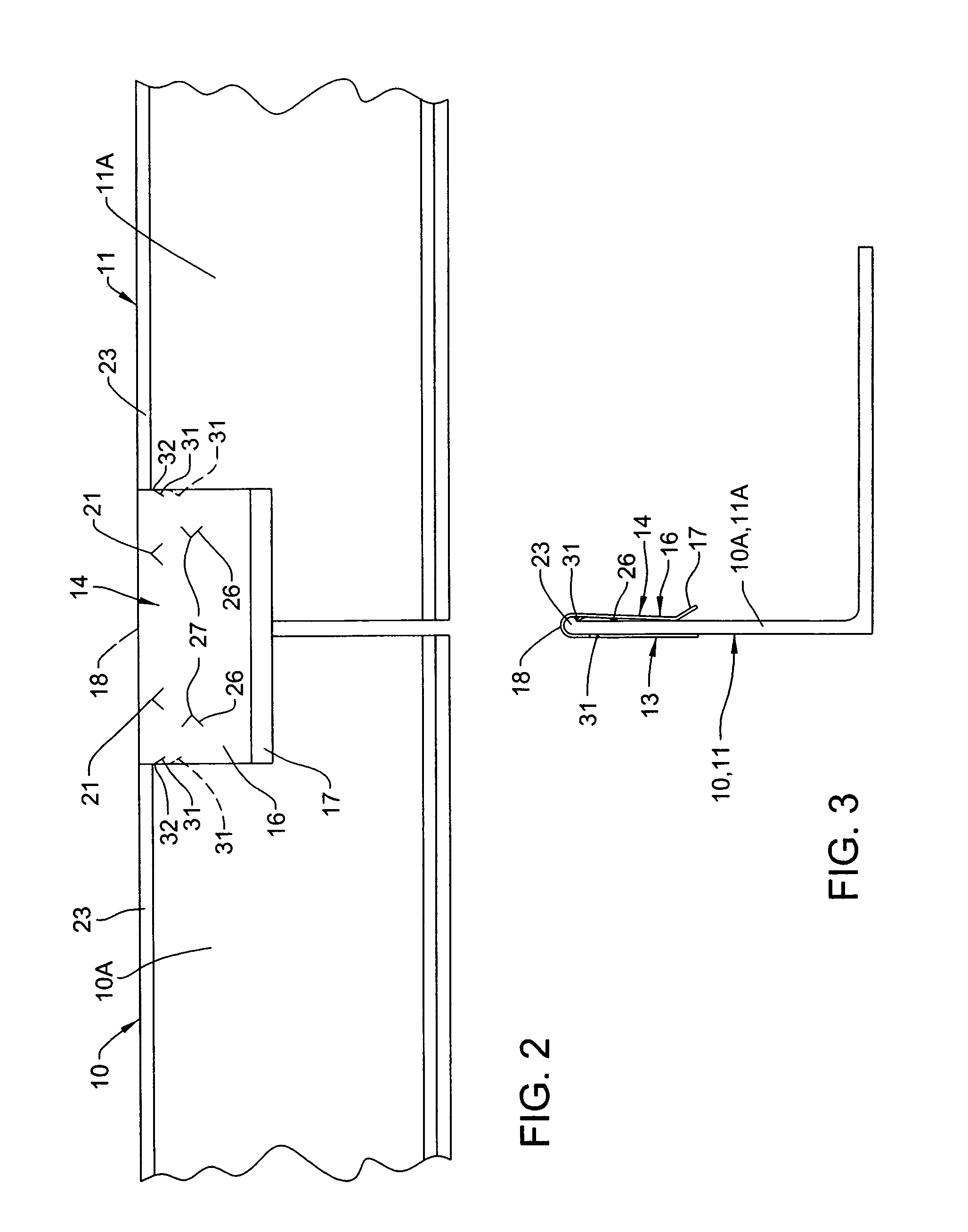
[0015]FIG. 1 illustrates two L-shaped landscape edging strips, or edge restraints 10 and 11 oriented end to end. While FIG. 1 illustrates the strips 10 and 11 being separated from one another by a finite distance, the arrows “A” are to signify that the edging strips are to be moved toward one another until there is a minimal gap therebetween as shown in FIG. 2 so that thereafter a U-shaped clip 12 can be slid into overlapping engagement with the vertical leg of each of the two strips to effect a connecting of the two strips together by the clip. That is, one half of the clip 12 overlaps the vertical leg 10A of the strip 10 while the other half of the clip overlaps the vertical leg 11A of the strip 11 as shown in FIG. 2.

[0016]FIGS. 4-6 illustrate the clip 12 per se. As shown, the U-shaped clip 12 is generally of a rectangular configuration (see FIG. 5) and is made of spring steel that has been heat treated to a Rockwell C hardness value of 40-49. The clip can be made of one of a stai...


PUM


Abstract

A U-shaped clip that is configured to be quickly installed by attaching the clip over the top edge of the vertical wall defined by plural end to end oriented landscape edging restraint members. This action is quick and easily accomplished by hand, requiring no tools or forceful effort. The clip is made of a material having a hardness characteristic that is harder than the material of the edging restraint members. The clip includes a series of pointed, opposing, hardened steel barbs that bite into the softer edging material to create a mechanical lock. Further, the barbs are angled so as to increase the force applied to the edging material as the parts are drawn apart in opposite directions.

Description

CROSS REFERENCE TO RELATED APPLICATIONS[0001]This application claims the benefit of U.S. Provisional Application No. 60 / 920,427, filed Mar. 28, 2007.FIELD OF THE INVENTION[0002]This invention relates to a device for interconnecting end to end landscape or hardscape edging strips, also known as edge restraints.BACKGROUND OF THE INVENTION[0003]This invention was born from the need to quickly and firmly attach longitudinal restraint sections of edging material for landscape and particularly hardscape applications. Edge restraints are a critical element in the construction of interlocking pavement and other hardscape constructions. They perform the mechanical function of restraining the perimeter of the hardscape so as to prevent lateral shifting and separation of the hardscape materials.[0004]Typical edge systems are often constructed of multiple lengths of edging materials that must be joined together to form a continuous length of restraint. The point of connection between adjacent s...

Claims


Application Information

Patent Timeline
Patent Type & Authority Patents(United States)
IPC IPC(8): A44B99/00A01G1/08A01G9/28
CPCA01G1/08Y10T24/44769A01G9/28
Inventor ZWIER, DANIEL G.
Owner PERMALOC CORP
Why Eureka
Try Eureka